background image


Theory of Operation:  (High Speed) 


Pressure sensitive tape is applied to the corrugated box as it passes by the 
cartridge.  The box will contact the front arm roller which has pressure sensitive 
tape adhesive side facing outward towards the oncoming box.  The front leading 
side of the box will contact the front roller arm and the tape will adhere to the 
box.  As the box continues to move forward the front roller arm and knife arm will 
be rotated into the frame of the cartridge.  The amount of force exerted on the 
box as tape is being applied is adjustable by changing the position of the main 
spring.  The front arm initial application force can be set to accommodate the 
strength of the box as well as the sturdiness of the contents in the box.   

As the front arm application roller transitions from the leading panel of the box 
to the top major flaps a separate wipe down spring is engaged.  The sole 
purpose of this spring is to add speed to the rear wipe roller actuation to insure 
the rear tape tab is completely wiped to the rear trailing panel of the box.  At this 
time the knife arm is retracted into the cartridge and the knife blade guard is 
fully retracted uncovering the blade.  As the knife arm rotated into the cartridge 
the knife activation spring extends, generating cut force.   

As the box proceeds pass the cartridge the front arm roller will no longer 
contact the major flaps of the box, but the rear wipe roller will still contact the 
major flaps.  Eventually as the box travels the knife arm will completely stop 
contacting the major flaps of the box.  This will allow the knife arm to travel back 
towards its home position allowing the knife blade to puncture and cut through 
the tape.  As the box continues move the rear wipe arm roller will no longer 
contact the major flaps of the box.  This will allow the wipe arm roller to spring 
out of the cartridge and contact the rear tab length of tape and press against the 
trailing panel of the box.  The rear wipe arm roller booster spring starts the wipe 
and the main cartridge spring finishes the wipe sequence. 

The box travelling pass the cartridge is the vehicle which pulls the tape through 
the cartridge.  The cartridge is design to run most pressure sensitive tapes with 
no required adjustments.  However in some cases it may be necessary to adjust 
tape tensions.  The cartridge will operate at speeds up to 170 feet/minute. 


Summary of Contents for Little David LD16AE 2.0

Page 1: ...Little David Case Sealer LD16AE 2 0 Automatic Random Case Sealer Operator sManual ...

Page 2: ...w Loveshaw Inc 2206 Easton Turnpike PO Box 83 South Canaan PA 18459 Tel 1 800 962 2633 570 937 4921 Fax 570 937 4016 www loveshaw com Loveshaw Europe Unit 9 Brunel Gate West Portway Industrial Estate Andover Hampshire SP10 3SL ENGLAND Tel 264 357511 Fax 264 355964 ...

Page 3: ...ting Procedures 9 Start Up 9 Sequence of Operation 9 Shut Down Procedure 10 Control Stop 10 Emergency Stop 10 Machine Sections 11 tape cartridge 16 Cartridge Sections 16 Tape Setup 17 Troubleshooting 20 Taping Difficulty 20 Boxes jamming in machine 23 Belt drive problems 23 Box does not enter machine 24 Front suppressor does not compress properly 24 Taping head adjustment malfunction 24 Taping hea...

Page 4: ...iii Maintenance 25 DAILY MAINTENANCE 25 WEEKLY MAINTENANCE 26 MONTHLY MAINTENANCE 27 Warranty 28 This space is intentionally blank Continue to next page ...

Page 5: ...andably a machine as sophisticated as this may require some adjustments from time to time If adjustments are necessary you will find simple instructions outline in this manual If you are in doubt about any adjustment or if a problem occurs which is not covered in this manual please call our service department It is important to be able to describe the problem in full detail Most problems can be co...

Page 6: ... Do not attempt to open or work on electrical box junction boxes or other electrical components without first disconnecting power to the machine Shock hazard exists if power is not disconnected Do not by pass any designed in safety features such as interlocks guards or shields Fully automatic machines are equipped with a rear flap kicker Do not place any part of the body near this area without fir...

Page 7: ... function is working correctly 5 Test guard door interlock switches by starting the machine with all of the guard doors closed If the machine starts then open each of the guard doors one at a time Each time a guard door is opened the machine must stop Test each guard switch with the machine running If the machine does not stop or reset the machine cannot be used until a qualified technician correc...

Page 8: ...vers several parts of the machine The following diagram identifies the some key sections of the machine Chapter 3 Head Assembly Frame Assembly Kicker Assembly Head Lifting Assembly Height Sensing Assembly Infeed Gate Assembly Actuator Assembly Air Tank ...

Page 9: ...t 22 25 565 mm Optional To Change Weight 650 lbs 302 kg Electrical Requirements Standard Voltage 115V 220V 1 PH 60 CYCLES 220V 3 PH 60 CYLES Optional 240V 1 PH 50 CYCLES 380V 3 PH 50 CYCLES 440V 3 PH 50 CYCLES 440V 3 PH 60 CYCLES Operating speed Belt Speed 80 ft min 24 4 m min Number Of Boxes Per Min Up to 14 depending on box dimensions ...

Page 10: ... liter free air 5 3 kg per sq cm Machine box capacity Length 8 25 Min 24 Max 206 mm 610 mm Width 4 5 Min 20 Max 144 mm 508 mm Height 4 5 Min 20 Max 144 mm 508 mm Closure Material Pressure Sensitive Tape Width 1 5 min 2 Max 38 mm 50 mm Max Roll Diameter 15 380 mm ...

Page 11: ...ial that is used to secure the head and cartridge The bed of the machine should be aligned with the roller height of the conveyor The machine should be centered on the infeed conveyor roller The machine should then be leveled The stripper plate should be used to adjust any minor height differences After the machine is in place and level connect the machine to an appropriate grounded electrical con...

Page 12: ...ller in down position belt should provide a smooth box flow into the machine Box Preparation Note Major flaps should not be inside minor flaps or bent outward far enough to miss the flap folders Minor flaps should be vertical or slightly inwards in the case of double wall boxes Minor flap score lines must be broken ...

Page 13: ... travel direction of belts they should move from the infeed end to the exit end of the machine If the direction is reversed stop the machine Have a licensed electrician reverse two wires on the main circuit breaker Sequence of Operation When a box enters the machine a sequence of operations is initiated This sequence takes the form of discrete steps Each must be sensed and completed before the nex...

Page 14: ...ergized Bringing down the gate The safety gate switches LS 3 to LS 6 de activate the E Stop circuit by opening any one of the four safety gates This will stop the machine and de activate the main air dump valve To re start the machine safety gates must first be close and the E Stop push button must be fully extended then the Star push button on the control station is pressed Shut Down Procedure Co...

Page 15: ...anged Belt drive system standard The two drive belts are directly driven by one drive wheel each that is mounted to the gear reducer output shaft The front end of the belt runs over a tension roller The tension roller bracket holds two guide rollers that automatically center the belts The belts then run over the idler roller onto the plastic anti friction carrier attached to the sheet metal belt c...

Page 16: ...factory supplied belts are recommended and both belts should be replaced at the same time The two belt tensioning brackets are spring loaded with two tension springs on each Make sure that these springs are attached to the tension roller bracket after the belts have been replaced If one or both belts at the exit end of the machine travel to the left or right the belt lagging on the drive rollers m...

Page 17: ...Page 13 Limit switches and Solenoid valve locations ...

Page 18: ...down very quickly without causing excess jarring to the machine If needed control b should be turned counterclockwise as far as practical and then the lock nut should be tightened Since the upward stroke of the kicker should be as slow as practical control a should be turned clockwise if needed and then the lock nut should be tightened If kicker hits solidly or bounces at either end of the stroke ...

Page 19: ...h the machine and press the stop button when the box is between the two squeezer wheels Then push each squeezer wheel snug against the box Tighten the m8 t nuts The machine is now ready to process this size box If a different size box must be sealed the squeezer wheels must be reset Counterweight and head adjustment The counterweight springs as shown below are designed to ease the manual up and do...

Page 20: ... exerted by the rollers is adjusted by changing the main spring to a different hole in the connecting link Tape guide plate The tape guide plate along with the finger plate is used to force the tape to stand up for proper application The tape guide plate moves which forms a corner as the box depresses the wipe down roller arm This insures a smooth tight tape application on the leading corner of th...

Page 21: ...djusted by loosening the small nut on the knife arm stud and rotating the stud until the large nut contacts the bumper at the desired setting The knife arm tension is controlled by the compression spring on the stud Tighten the nylock nut for greater tension Always power down the machine first Tape Setup Loading top tape 1 Retract detent with right hand 2 With left hand grab cartridge near tape co...

Page 22: ...is preferable and much simpler Splicing procedure 1 With a pair of scissors cut tape on expiring roll Remove butt roll of tape from tape core 2 Remove cartridge from head 3 Install a new roll of tape on tape core with tape feeding clockwise 4 Splice a lap to cut end with trailing edge of old tape on top 5 Pull splice completely through cartridge cut splice off 6 Replace cartridge Reloading of tape...

Page 23: ...artridge is set to use a 15 diameter tape roll maximum When using a larger roll it may be necessary to slightly increase tape core tension to eliminate tape over run Lubrication Bearings used in the idler rollers are permanently lubricated and sealed Bearing blocks chains sprockets and threaded shafts should be greased regularly to ensure free movements The masts should be cleaned and sprayed with...

Page 24: ...pe down rollers If necessary increase the main spring pressure Check that the spring is not broken 2 Tape end sticks to itself or mechanism A Check that there is not too much drag on the tape causing stretching and snap back at cut off Reduce the tape core drag setting B Check the tape threading path See tape threading diagram C Check for defective tape roll by pulling tape off manually The pull s...

Page 25: ...ing problems If necessary re adjust the pressure C Check that all the rollers turn freely on their shafts D Check the box contents Partially full boxes or very compressible contents may allow flaps to depress excessively causing wrinkles E Check the drag of the tape Too much drag may cause overrunning of the tape roll Adjust the tape core setting F Tape tension set too high G Check roller stop ins...

Page 26: ...tops and make sure roller arm contacts flat surfaces When processing boxes less than 5 high the eccentric stops must be moved to the opposite hole in the cartridge frame The front roller should then protrude to belt level 7 Tape not cutting A Check knife arm for mechanical binding B Check that knife is not dull C Check springs on knife studs D Check bushings in knife studs E If knife stop block is...

Page 27: ...chine will not process unstable boxes 3 Contents bulging through top of box A Check to be sure that the box is not overfilled with contents 4 Box slipping against belts A Increase the down pressure by adjusting the front suppressor 5 Head pressure too high A Raise head slightly Adjust front suppressor height Belt drive problems 1 Belts do not move A Check that machine is connected to a live electr...

Page 28: ...ont suppressor does not compress properly A Check sensing height B Adjust head height properly Taping head adjustment malfunction A Check the chains on both idler sprockets on both sides of machine B Check that drive wheel is tight on shaft Taping head crushes box A Check head height adjust if necessary Kicker does not close rear flap A Check if kicker closes too early or too late adjust according...

Page 29: ...ITH DENATURED ALCOHOL AND A CLEAN CLOTH WIPE THE BLADE WITH THE SHOP RAG FROM THE BOTTOM OF THE BLADE TOWARD THE TEETH INSPECT THE ROLLERS AND CHECK FOR TORN OR SLICED ROLLERS ALSO CHECK THE ROLLERS FOR TAPE BUILD UP IF ROLLERS ARE TORN OR RIPPED REPLACE THE ROLLERS IF ROLLERS ARE WRAPPED WITH TAPE OR HAVE ADHESIVE BUILD UP ON THEM CLEAN WITH DENATURED ALCOHOL INSPECT END OF TRAVEL BUMPER FOR FRON...

Page 30: ...ED AT ASSEMBLY PHOTOELECTRIC SENSORS CHECK PHOTOELECTRIC SENSORS FOR OBSTRUCTIONS FOR EXAMPLE DUST OR CORRUGATED DEBRIS CLEAN LENSES ON PHOTOELECTRIC SENSOR WITH A SOFT CLOTH AND MILD SOAPY WATER BE CAREFUL NOT TO SCRATCH THE LENSES CHAINS HEAD LIFTING AND DRIVE CHAINS CHECK HEAD LIFTING AND DRIVE CHAINS FOR PROPER TENSION CHAINS SHOULD NOT BE LOOSE OR SAGGING ...

Page 31: ...NFEED BELT CHECK INFEED BELT FOR FRAYING OR EXCESS WEAR CHECK THAT BELT LACING IS NOT PULLING APART CHANGE BELT IF NECESSARY MAIN DRIVE REDUCER CHECK THE LEVEL OF LUBRICANT IN REDUCER REMOVE BREATHER AND REDUCER PLUG DIRECTLY ABOVE HEIGHT OF OUTPUT SHAFT FILL REDUCER WITH MOBIL 634 SYNTHETIC OIL THROUGH BREATHER HOLE UNTIL OIL LEVEL REACHES THE HEIGHT OF THE UNPLUGGED LOWER HOLE COMPRESSED AIR FIL...

Page 32: ...TO HAVE BEEN DEFECTIVE IN MATERIAL OR WORKMANSHIP AT THE TIME THE GOODS WERE SHIPPED FROM LITTLE DAVID S PLANT ANY WARRANTY CLAIM NOT MADE IN WRITING TO LITTLE DAVID AT ITS HOME OFFICE WITHIN THE APPLICABLE WARRANTY PERIOD AND WITHIN 10 DAYS OF FAILURE WILL NOT BE VALID THIS IS THE SOLE AND EXCLUSIVE REMEDY AVAILABLE UNDER THIS WARRANTY UNDER NO CIRCUMSTANCES WILL LITTLE DAVID BE LIABLE FOR INCIDE...

Page 33: ...Page 29 MECHANICAL DRAWINGS AND SCHEMATICS Chapter 10 ...

Page 34: ...2 29 6 7 1 6 72 75 7 28 6 21 17 3535 7 5 1 250 7 21 7 6 5 1 25 68 7 0 77 5 7 52 6 127 5 352 8 27 5 7 1 25 285 2 1 86 25 72 6 26 72 27 5 7 287 7 35 66 5 77 1 216 17 2 29 6 7 1 5 7851 72 29 6 7 8321 5 48 67 5 0 66 0 5 0 5 5 3DUWV LVW 6 5 37 21 3 57 180 5 47 7 0 3 5 0 11 5 7 3 5 0 11 7 3 5217 5 0 3 5 5 5 0 3 723 6 5 6 3 723 5217 5 5 5 6 3 6 7 6 5 3 27720 17 5 5 3 723 17 5 5 3 7 16 21 3 5 8 5 5 3 5 9 ...

Page 35: ...RESSOR BAR LD12B 1018 4 1 6 HOLD DOWN RAIL HEAD LD16P 0057 5 2 7 SPACER KICKER CYLINDER LD16B 1013 3 4 8 KICKER CYLINDER N211A NOR 1 9 CLEVIS PIN N229 1 10 COLLAR SC50 4 11 SET COLLAR SC62 4 12 SUPPRESSOR SPRING UG58 10 1 13 SUPPRESSOR LD12B 1012 6 1 14 COTTER PIN HP105 3 15 KICKER VALVE ASSY SV 1 16A 1 16 SEE NEXT PAGE SQUEEZER ASSY 1 17 CLEVIS PIN PSR101CLP 3 1 18 FLAP FOLDER LEFT LD12B 1013 6 1...

Page 36: ... 57 2 29 6 1 6 72 75 7 28 6 21 17 3535 7 5 1 250 7 21 7 6 5 1 25 68 7 0 77 5 7 52 6 127 5 352 8 27 5 7 1 25 285 2 1 86 25 72 6 26 72 27 5 7 287 7 35 66 5 77 1 216 17 2 29 6 1 5 7851 72 29 6 8321 5 48 67 76 3 6 723 648 5 66 0 76 3 6 67 67 LGZ GHQQLVZ 3DUWV LVW 6 5 37 21 3 57 180 5 47 7 0 648 5 5 0 7 648 5 5 0 5 7 648 5 1 6 5 238 648 5 7 187 238 63 5 238 66 86 1 238 1 2 187 0 1 10 3 5 9 6 21 6725 5 ...

Page 37: ...1 1 68 7 0 77 5 7 5 21 6 7 86 9 3523 57 2 29 6 7 1 6 72 75 7 28 6 21 17 3535 7 5 1 250 7 21 7 6 5 1 25 68 7 0 77 5 7 52 6 127 5 352 8 27 5 7 1 25 285 2 1 86 25 72 6 26 72 27 5 7 287 7 35 66 5 77 1 216 17 2 29 6 7 1 5 7851 72 29 6 7 8321 5 48 67 11 6 69 5 9 9 66 69 LGZ 3DUWV LVW 6 5 37 21 3 57 180 5 47 7 0 9 9 1 63 21752 1 5 66 77 1 5 7 5 9 9 3 60 5 9 6 21 6725 5 9 6 5 37 21 7 5 6 ...

Page 38: ...7 2 29 6 1 5 7851 72 29 6 8321 5 48 67 EU FHI 7 1 66 5 3DUWV LVW 6 5 37 21 3 57 180 5 47 7 0 0 67 36 5 7 36 6 3 7 36 3 2 2 3 6 5 7 7 1 3 6 7 3 75 78 725 10 17 283 1 1 78 725 02817 3 2 1 9 9 1 5 7 5 365 2 5 6 3 7 3 77 1 3 137 78 1 8 2 7 63 62 3 6 5 0 6 0 3 187 16 3 6 0 0 3 2 6 5 0 0 3 0 PP 6 6 6 0 3 7 6 5 0 0 3 1 2 187 0 1 10 3 0 6 6 6 0 3 7 6 5 0 0 3 2 7 0 0 3 0 1 5 6 5 10 3 7 6 5 0 0 3 2 6 5 0 0 ...

Page 39: ... 5 21 6 7 86 9 3523 57 2 29 6 7 1 6 72 75 7 28 6 21 17 3535 7 5 1 250 7 21 7 6 5 1 25 68 7 0 77 5 7 52 6 127 5 352 8 27 5 7 1 25 285 2 1 86 25 72 6 26 72 27 5 7 287 7 35 66 5 77 1 216 17 2 29 6 7 1 5 7851 72 29 6 7 8321 5 48 67 1 7 66 0 B37B B3 6 0 5 37 3 6 3DUWV LVW 6 5 37 21 3 57 180 5 47 7 0 6 7 7 86 1 36 9 6 3 1 127 6 2 1 365 3 86 1 7 1 5 23 52 5 5 1 1 7 3 1 5 9 6 3 5 9 6 21 6725 5 9 6 5 37 21...

Page 40: ...7 5 7 52 6 127 5 352 8 27 5 7 1 25 285 2 1 86 25 72 6 26 72 27 5 7 287 7 35 66 5 77 1 216 17 2 29 6 7 1 5 7851 72 29 6 7 8321 5 48 67 6 7 7 66 0 6 3 6 0 5 6 3 6 3DUWV LVW 6 5 37 21 3 57 180 5 47 7 0 6 7 6 7 63 5 58 5 803 5 0 3 1 3 66 5 7 6 7 7 11 6 7 7 6 6 7 63 5 6 7 7 6 7 6 70 211 725 5 9 7 3 6 5 0 0 3 20 187 0 10 3 62 3 6 5 0 00 6 0 3 187 0 10 3 20 187 0 10 3 62 3 6 5 0 6 0 3 187 0 10 3 2 6 5 0 ...

Page 41: ......

Page 42: ...9 6 1 6 72 75 7 28 6 21 17 3535 7 5 1 250 7 21 7 6 5 1 25 68 7 0 77 5 7 52 6 127 5 352 8 27 5 7 1 25 285 2 1 86 25 72 6 26 72 27 5 7 287 7 35 66 5 77 1 216 17 2 29 6 1 5 7851 72 29 6 8321 5 48 67 27720 7 5 9 LGZ GHQQLVZ 3DUWV LVW 6 5 37 21 3 57 180 5 47 7 0 52 5 6 7 1 3 927 52 5 50 7 58 1 675 3 7 1 52 5 5 36 7 11 5 7 3 7 11 7 3 52 5 8 5 7 52 5 8 5 5 7 5 9 7 8 5 36 3 8 5 8 5 5 3 575 63 5 3 5 9 6 21...

Page 43: ... SIDE RAIL WELDMENT RIGHT LD12B 2031 6 1 1 SIDE RAIL RIGHT LD12B 2033 6 1 2 SIDE RAIL LEFT LD12B 2034 4 1 3 SIDE RAIL CAP PSC511A 4 4 CONNECTING ARM LD12B 2049 4 1 5 SIDE RAIL SPACER PSC212 3 4 6 SIDE RAIL PIVOT TUBE INSERT PSC38 3 4 7 SPACER BEARING PSC40A 3 8 8 BALL BEARING PSC613 6 9 RETAINING RING PSC566 1 10 SPHERICAL ALIGN BEARING PSC552 1 11 SIDE RAIL WELDMENT LEFT PSX8784 4 1 12 CLAMP BLOC...

Page 44: ... 3523 57 2 29 6 1 6 72 75 7 28 6 21 17 3535 7 5 1 250 7 21 7 6 5 1 25 68 7 0 77 5 7 52 6 127 5 352 8 27 5 7 1 25 285 2 1 86 25 72 6 26 72 27 5 7 287 7 35 66 5 77 1 216 17 2 29 6 1 5 7851 72 29 6 8321 5 48 67 EU FHI 67 5 5 3DUWV LVW 6 5 37 21 3 57 180 5 47 7 0 6 28 5 2 7 63 1 2 187 1 16 3 63 5 6 28 5 2 7 3 187 81 1623 187 81 1623 63 5 5 1 63 63 5 5 1 63 67 5 3 63 5 6 28 5 2 7 3 5 9 6 21 6725 5 9 6 ...

Page 45: ... DISCLOSED TO OTHER WITHOUT THE EXPRESSED WRITTEN CONSENT OF LOVESHAW AND WILL BE RETURNED TO LOVESHAW UPON REQUEST brycef 3 12 2015 AIR TANK ASSY LD16AR Parts List DESCRIPTION PART NUMBER QTY ITEM AIR TANK N587 1 1 TANK MOUNT STRAP LD14 0165 5 2 2 RUBBER TANK PAD LD14 0173 3 2 3 BRASS NIPPLE H127 3 4 BUSHING 1 2 NPT TO 1 4 NPT H134 1 5 CROSS FITTING H104 2 6 1 4 NPT Ball Valve PSR706 A 1 7 ONE WA...

Page 46: ...ITEM ROLLER K286D 2 1 BRACKET PSC193 5 1 2 TENSION ROLLER PSC195 4 1 3 GUARD PSC201 4 1 4 BUSHING PSC21 4 2 5 LOCK WASHER 1 4 FLWSDP 2 6 HEX NUT 1 4 20 FHFNSEP 2 7 FLAT WASHER M8 FFWMHP 1 8 LOCK WASHER M8 FLWMHP 1 9 HEX NUT M8 FHFNMHP 1 10 HEX HD M8 x 120 FHHMH120P10 1 11 SPRING PSC640 2 12 8 7 4 5 11 2 3 9 10 1 6 REVISION HISTORY REV DESCRIPTION DATE BY A RELEASED 11 4 2004 AMYR 12 ...

Page 47: ......

Page 48: ...ALTER BOX FOR MIRROR IMAGE FOR FRESHLY OREDER ...

Page 49: ......

Page 50: ......

Page 51: ......

Page 52: ......

Page 53: ......

Page 54: ......

Page 55: ......

Page 56: ......

Page 57: ......

Page 58: ...es Standard High Speed THE LOVESHAW CORPORATION LOVESHAW EUROPE 2206 EASTON TURNPIKE BOX 83 UNIT 9 BRUNEL GATE SOUTH CANAAN PA 18459 W PORTWAY INDUSTRIAL ESTATE ANDOVER HAMPSHIRE SP103SL TEL 570 937 4921 ENGLAND FAX 570 937 4370 44 264 3575 11 ...

Page 59: ...CAC61 series 3 wide tape This is a combined manual for the CAC60 series 2 wide tape and the CAC61 series 3 wide tape Take care when ordering parts Make sure it is for the correct width cartridge For stainless steel cartridge parts add the suffix SS to the part numbers depicted in the assembly drawings ...

Page 60: ... is fully retracted uncovering the blade As the knife arm rotated into the cartridge the knife activation spring extends generating cut force As the box proceeds pass the cartridge the front arm roller will no longer contact the major flaps of the box but the rear wipe roller will still contact the major flaps Eventually as the box travels the knife arm will completely stop contacting the major fl...

Page 61: ...retracted into the cartridge and the knife blade guard is fully retracted uncovering the blade As the knife arm rotated into the cartridge the knife activation spring extends generating cut force As the box proceeds pass the cartridge the front arm roller will no longer contact the major flaps of the box but the rear wipe roller will still contact the major flaps Eventually as the box travels the ...

Page 62: ...uation to insure the rear tape tab is completely wiped to the rear trailing panel of the box At this time the knife arm is retracted into the cartridge and the knife blade guard is fully retracted uncovering the blade As the knife arm rotated into the cartridge the knife activation spring extends generating cut force As the box proceeds pass the cartridge the front arm roller will no longer contac...

Page 63: ...and the following precautions Never service the tape cartridges when installed in an operating machine Use lock out tag out protocols before installing or removing cartridges from machinery Do not bypass or remove safety guard on knife blade Observe caution when near tape cartridge knife The knife blade is protected by a locking cover which is held closed by the link bar Never make any adjustments...

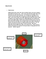
Page 64: ... the tape roll on the core Now turn the adjustor nut clockwise until the tape roll is snuggly held refer to figure1 Tape roll must be placed on tape core with adhesive side of tape facing to the right Refer to figure 2 for proper orientation Thread the tape over white roller Threading arrows are installed throughout the tape path of the cartridge to aid in threading The back of the tape the non ad...

Page 65: ...The tape is then threaded around the knurled tape tension roller The adhesive side of the tape contacts the knurled roller Refer to figure 4 Figure 3 White tape roller Knurled tension roller Figure 4 ...

Page 66: ...e will contact the two tape guide rollers as it is pulled through the guide plate assembly until it is at rest on the front arm roller The adhesive side of the tape will be facing away from the front arm roller Refer to figure 5 Figure 5 Black knurled roller Front arm roller Tape guide plate Tape guide rollers ...

Page 67: ...core height adjusting nut clockwise the tape core height position will decrease moving the tape closer to the mill stand side of the cartridge By turning the tape core height adjusting nut counter clockwise the tape core height position will increase This will make the tape track further away from the mill stand After each adjustment always tighten the tape core locking screw Failure to do so will...

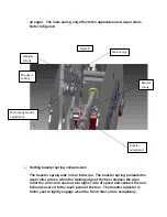
Page 68: ...y need to be adjusted if a thick mill tape is being used By increasing the tension it aids in cutting the tape To increase the tension turn the adjustment nut clockwise To decrease the tension turn the adjustment nut counterclockwise Refer to figure7 Setting main spring tension Setting the main spring tension is done by moving the end of the spring to a different preset position The main spring te...

Page 69: ...roller arm so when the trailing edge of the box releases the wipe roller the arm can travel out at a higher rate of speed and contact the rear tab and secure it to the back panel of the box The booster adjuster is factory set to lightly engage when the front roller arm is completely Figure 8 Main spring tension adjustment Strongest setting Weakest setting Main spring Booster spring Booster adjustm...

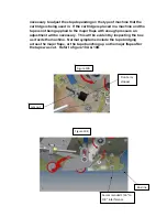
Page 70: ...move in order to shorten the rear tab length The adjustor only alters the rear tab length The front tab length is fixed and cannot be adjusted Refer to figure 9 Front arm stopper adjustment The front arm stop adjustment is factory set to insure that the front arm roller stays in contact with major flaps of the box This allows for a tight tape seal across the horizontal length of the box The adjust...

Page 71: ...major flaps with enough pressure an adjustment will be necessary This will be evident by inspecting the box as it exits the machine Normal symptoms include the tape bridging across the major flaps or the tape bunching up on the major flaps after the tape was cut Refer to figure 10A 10B Figure 10A Jam nut Front arm stopper Figure 10B Box line Recommended 1 16 to 1 8 interference ...

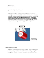
Page 72: ...ft all the way until the retaining pin protrudes through other side of the roller and extends out to hold the roller in place Take caution to install replacement roller with undercut facing toward arm away from retaining pin Refer to figure 11 Knife blade replacement Knife blade replacement is a tool less procedure Simply push down on release bar and pull knife blade out Fold back the knife guard ...

Page 73: ...slots to allow for easy slide on off replacements The knife blade is notch for proper orientation of the blade Refer to figure 12A and 12B Oil Pad Regularly lubricate oil pad with SAE 30 non detergent oil Never use penetrating type oil this will dissolve the adhesive which secures the pad to the knife guard Refer to figure 12A Warning Use extreme care when working near the knife blade The blade is...

Page 74: ...Knife guard is shown open in both figures Figure 12B Blade release bar ...

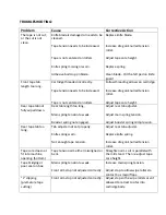
Page 75: ...ear tab length too long Main spring tension to weak Booster spring not engaged Adjust rear tab adjuster Adjust main spring tension Adjust booster spring compression Rear tape tab too long Tab adjuster not set properly Knife spring worn Not enough tape tension Adjust rear tab adjuster Replace knife spring Increase drag on knurled tension roller Tape core does not fit into machine opening bottom Tap...

Page 76: ...n control of the cartridge as it is lowered into its housing DO NOT allow it to slam or free fall into place Failure to do so could damage and void warranty on parts of the cartridge Tape is being adhered to front of box Tape getting wrapped around rear wipe roller Front roller arm doesn t have enough tension Tape broken in cartridge Tape adhesive not aggressive enough Increase main spring pressur...

Page 77: ...nd a mirror image suffix MI Any of the parts that have a suffix indicated in their row require the suffix to be added to the end of the part number for a stainless steel and or mirror image cartridge Example 1 Refer to Table 1 for the following example If you wanted to order a Link Bar for your stainless steel cartridge Find the part in the corresponding table The part number for a standard carbon...

Page 78: ...rtridge is CAC60 0001 6 The cartridge your ordering is stainless steel and mirror image Check the columns under the heading SS and MI If a SS and MI are in the rows for the part you are ordering than SS and MI must be added to the end of the part number In this example SS and MI are indicated in the row for the Front Roller Arm So the part number would be as follows CAC60 0001 6SMI Take note that ...

Page 79: ...0 8mm FLANGE BUSHING 7 1 SPR 1044 SPRING COMPRESSION SS 8 1 CAC60 0134 4 SLIDING BLOCK MI 9 1 CAC60 0002 4 ROLLER 10 2 SPH 1339 M8 WASHER SS 11 2 BSG 1098 BUSHING 12 1 CAC60 0073 3 SMALL ROLLER 13 4 FBHME012P10 M4 x 12 BUTTON HEAD P S 14 1 FFHMG016P10 FHCS M6 X 1 0 X 16 LG P S 15 1 BSG 1085 BUSHING 16mm 16 1 FBHME020P10 M4 x 20 PAN HEAD SCREW P S 17 1 FHFNMEP M4 HEX NUT P S 18 1 SPR 1055 EXTENSION...

Page 80: ...BEARING 1 TRA60A TENSION ROLLER ASSEMBLY SS MI 2 PSC28 3 BRAKE WASHER 2 BSG 1098 BUSHING 6 SPH 1276 SNAP RING EXTERNAL SS 1 SPH 1268 RETAINING RING EXTERNAL SS 1 SPR 1042 EXTENSION SPRING SS 1 CAC60 0078 3 KNIFE GUARD CUSHION 4 SPR 1045 COMPRESSION SPRING SS 2 CAC60 0042 3 PIN 1 CAC60 0043 3 PIN PLATE 2 BSG 1091 FLANGE BUSHING 1 SPR 1063 KNIFE GUARD SPRING MI 1 SPR 1069 MAIN SPRING SS 1 CAC60 0082...

Page 81: ...BEARING 1 TRA61A TENSION ROLLER ASSEMBLY SS MI 2 PSC28 3 BRAKE WASHER 2 BSG 1098 BUSHING 6 SPH 1276 SNAP RING EXTERNAL SS 1 SPH 1268 RETAINING RING EXTERNAL SS 1 SPR 1042 EXTENSION SPRING SS 1 CAC60 0078 3 3 KNIFE GUARD CUSHION 4 SPR 1045 COMPRESSION SPRING SS 2 CAC60 0042 3 PIN 1 CAC60 0043 3 3 PIN PLATE 2 BSG 1091 FLANGE BUSHING 1 SPR 1063 KNIFE GUARD SPRING MI 1 SPR 1072 MAIN SPRING SS 1 CAC60 ...

Page 82: ...ARING 1 TRA61A TENSION ROLLER ASSEMBLY SS MI 2 PSC28 3 BRAKE WASHER 2 BSG 1098 BUSHING 6 SPH 1276 SNAP RING EXTERNAL SS 1 SPH 1268 RETAINING RING EXTERNAL SS 1 SPR 1042 EXTENSION SPRING SS 1 CAC60 0078 3 3 KNIFE GUARD CUSHION 4 SPR 1045 COMPRESSION SPRING SS 2 CAC60 0042 3 PIN 1 CAC60 0043 3 3 PIN PLATE 2 BSG 1091 FLANGE BUSHING 1 SPR 1063 KNIFE GUARD SPRING MI 1 SPR 1072 MAIN SPRING SS 1 CAC60 00...

Page 83: ...1 N401 359 COMPACT CYLINDER 1 N401 349B CYLINDER x 4 W CUSHION 2 CAC60 0047 3 BRONZE BUSHING ...

Page 84: ...RYCEF 7 27 2011 MAIN ASSY HS 2 0 MAIN ASSEMBLY MAIN ASSY HS 2 0 idw Parts List MI SS DESCRIPTION PART NUMBER QTY ITEM MI SS FORNT ROLLER ARM ASSEMBLY FRACAC60 2 1 1 MI SS REAR ROLLER ARM ASSEMBLY RRACAC60 2 1 2 MI SS KNIFE ASSEMBLY KAACAC60 1 3 SS TAPE CORE ASSEMBLY 2 TCA2 1 4 MI SS TENSION ROLLER ASSEMBLY TRA60A 1 5 TOP LOAD BRACKET 2 CAC60 0154 2 4 1 6 ROLLER ASSEMBLY RA 60 1 7 REVISION HISTORY ...

Page 85: ...ATTER THEROF SHALL NOT BE REPRODUCED OTHER THAN FOR YOUR OWN USE OR TO BE DISCLOSED TO OTHER WITHOUT THE EXPRESSED WRITTEN CONSENT OF LOVESHAW ITW AND WILL BE RETURNED TO LOVESHAW ITW UPON REQUEST BRYCEF 6 6 2012 CAC60 NT_NC MAIN ASSEMBLY MAIN ASSY idw Parts List MI SS DESCRIPTION PART NUMBER QTY ITEM MI SS FRONT ROLLER ARM ASSY FRAANTNC 1 1 MI SS REAR ROLLER ARM ASSY RRAA HD 1 2 MI SS KNIFE ASSEM...

Page 86: ...D BUMPER BRACKET CAC60 0151 3 1 30 ROLLER CAC60 0145 4 1 31 RETAINING RING 10mm SPH 1268 1 32 TAPE TENSION ARM SHAFT CAC60 0056 4 1 33 M5 NYLON LOCKING NUT S S FNLNMFS 1 34 M5 FENDER WASHER SPH 1518 1 35 TIE BLOCK TOP LAOD BRKT CAC60 0088 3 1 36 HD BUMPER CAC60 0152 3 1 37 A Parts List MI SS DESCRIPTION PART NUMBER QTY ITEM MI SS MAIN FRAME CAC60 0000 6 1 1 MI SS SIDE FRAME MEDIUM CAC60 0103 6 1 2...

Page 87: ...FHCS M5 X 16 LG FFHMF016P10 7 8 P S LOCK WASHER M5 FLWMFP 3 9 P S HEX NUT M5 FHFNMFP 3 10 SS MILLSTAND CAC60 0031 4 1 11 SS WASHER SPH 1502 1 12 SS SHAFT CAC60 0096 3 1 13 SS 16mm SET COLLAR SC16M 2 14 FLANGE BUSHING BSG 1121 3 1 15 DELRIN WASHER SPH 1457 1 16 SS BUSHING STUD CAC60 0133 3 1 17 P S M6 HEX JAM NUT FHJNMGP 6 18 M6x50 SET SCREW SPH 1495 2 19 MI SS SECONDARY FRAME CAC60 0107 4 1 20 SS ...

Page 88: ... LG FFHMG016P10 1 11 BUSHING 16mm BSG 1085 1 12 P S M4 x 20 PAN HEAD SCREW FBHME020P10 1 13 M4 NYLOCK NUT FNLNMEP 1 14 SS EXTENSION SPRING SPR 1055 1 15 SS SHAFT ASSEMBLY SA60 A 1 16 SS 10mm FLANGE BEARING BRG 2015 4 17 MI SS FINGER PLATE ASSY FPACAC60 SB 1 18 P S BUTTON HEAD M4 1 0 X 16 FBHME016P10 1 19 MI KNIFE GUARD LOCK FIXED CAC60 0144 4 1 20 P S HHCS M5 X 0 8 X 10 LG FHHMF010P10 2 21 P S LOC...

Page 89: ...TTON HEAD M4 1 0 X 16 FBHME016P10 1 10 P S FLAT WASHER M5 FFWMFP 1 11 P S FHCS M6 X 1 0 X 16 LG FFHMG016P10 1 12 SMALL ROLLER CAC60 0073 3 3 1 13 BUSHING BSG 1098 2 14 MI SS FINGER PLATE FPACAC61 1 15 M4 NYLOCK NUT FNLNMEP 1 16 P S M4 x 20 PAN HEAD SCREW FBHME020P10 1 17 SS EXTENSION SPRING SPR 1055 1 18 SS SHAFT SUPPPORT LOWER CAC60 0159 3 1 19 SS SHAFT ASSEMBLY 3 SA61A 1 20 P S FHCS M5 X 0 8 X 1...

Page 90: ...FHFNMEP 1 14 SS EXTENSION SPRING SPR 1055 1 15 SS SHAFT ASSEMBLY SA60 A 1 16 5 16 BRONZE WASHER SPH 1277 2 17 MI SS FINGER PLATE ASSEMBLY FPACAC60 SB 1 18 P S BUTTON HEAD M4 1 0 X 16 FBHME016P10 1 19 P S FLAT WASHER M5 FFWMFP 1 20 SS 10mm FLANGE BEARING BRG 2015 10 21 BUSHING REWORKED BSG 1136R1 3 1 22 ROLLER TAPE GUIDE PLATE CAC60 0172 4 1 23 P S FLAT WASHER M8 FFWMHP 2 24 MI SS LINK BAR CAC60 01...

Page 91: ... M4 x 20 PAN HEAD SCREW FBHME020P10 1 15 SS EXTENSION SPRING SPR 1055 1 16 MI SS SHAFT ASSEMBLY 3 SA61A 1 17 P S BUTTON HEAD M4 1 0 X 16 FBHME016P10 1 18 BUSHING REWORKED BSG 1136R1 3 1 19 MI SS LINK BAR CAC60 0167 4 1 20 5 16 BRONZE WASHER SPH 1277 2 21 M8 WASHER SPH 1339 2 22 SS SHAFT SUPPPORT LOWER CAC60 0159 3 1 23 P S FHCS M5 X 0 8 X 12 LG FFHMF012P10 7 24 P S M4 x 12 BUTTON HEAD FBHME012P10 ...

Page 92: ... 0073 3 1 13 BUSHING BSG 1098 2 14 P S M4 x 20 PAN HEAD SCREW FBHME020P10 1 15 SS EXTENSION SPRING SPR 1055 1 16 M4 NYLOCK NUT FNLNMEP 1 17 P S M4 x 12 BUTTON HEAD FBHME012P10 4 18 P S FHCS M6 X 1 0 X 16 LG FFHMG016P10 1 19 P S FLAT WASHER M5 FFWMFP 1 20 SS SHAFT ASSEMBLY SA60 A 1 21 SS 10mm FLANGE BEARING BRG 2015 10 22 P S BUTTON HEAD M4 1 0 X 16 FBHME016P10 1 23 10mm LINEAR BEARING BSG 1124 1 2...

Page 93: ...17 MI SS FINGER PLATE ASSY FPACAC61 1 18 M4 NYLOCK NUT FNLNMEP 1 19 P S M4 x 20 PAN HEAD SCREW FBHME020P10 1 20 SS EXTENSION SPRING SPR 1055 1 21 SS SHAFT SUPPPORT LOWER CAC60 0159 3 1 22 SS CLEVIS CAC60 0111 3 1 23 SS SET COLLAR 5 16 SC31 1 24 SS SHAFT ASSEMBLY 3 SA61A 1 25 P S FHCS M5 X 0 8 X 12 LG FFHMF012P10 7 26 KNIFE GUARD LOCK CAC60 0141 4 1 27 SLIDING BLOCK DBL BEARING CAC60 0166 4 1 28 BU...

Page 94: ...12 REAR ROLLER ARM Parts List MI SS DESCRIPTION PART NUMBER QTY ITEM MI SS REAR ROLLER ARM CAC60 0126 5 1 1 ROLLER CAC60 0002 4 1 2 WAVE WASHER SPH 1252 1 3 BUSHING 16mm BSG 1085 2 4 SS RETAINING RING 8mm SPH 1276 1 5 SS SPACER CAC60 0034 3 1 6 P S FHCS M6 X 1 0 X 16 LG FFHMG016P10 1 7 SS SHAFT ASSEMBLY SA60 A 1 8 SS ROD END M6 SPH 1267R 1 9 P S BUTT HD CAP SCREW M5 X 20 FBHMF020P10 1 10 REVISION ...

Page 95: ...ION SPRING SPR 1036 1 8 SS RETAINING RING 8mm SPH 1276 1 9 SPACER CAC60 0034 3 1 10 SHAFT COLLAR SPH 1338 1 11 P S FHCS M6 X 1 0 X 16 LG FFHMG016P10 2 12 P S BHCS M6 X 16 FBHMF016P10 1 13 P S HEX NUT M6 FHFNMGP 1 14 SS SHAFT ASSEMBLY SA60 A 1 15 SS ROD END M6 SPH 1267R 1 16 P S B H CAP SCREW M5 X 20 FBHMF020P10 1 17 P S SHCS M6 X 1 0 X 12 LG FSHMG012P10 1 18 P S M6 FENDER WASHER FFWMGP 1 19 Parts ...

Page 96: ...ITW UPON REQUEST BRYCEF 6 5 2012 RRAA HD REAR ROLLER ARM ASSY RRAA HD idw Parts List MI SS DESCRIPTION PART NUMBER QTY ITEM MI SS REAR ROLLER ARM CAC60 0155 5 1 1 SS STANDOFF CAC60 0018 3 1 2 ROLLER CAC60 0002 3 4 1 3 WAVE WASHER SPH 1252 1 4 SS BUSHING 16mm BSG 1085 2 5 SS ROD END M6 SPH 1267 1 6 SLIDING ROD CAC60 0010 4 1 7 SS COMPRESSION SPRING SPR 1036 1 8 SPACER CAC60 0034 3 1 9 P S BHCS M6 X...

Page 97: ...ASSY idw Parts List MI SS DESCRIPTION PART NUMBER QTY ITEM CYLINDER MOUNT CAC60 0112 5 1 1 1 4 X 1 4 NPT FITTING N400 25 1 2 SS SET COLLAR 1 4 SC25 1 3 P S SHCS M4 X 0 7 X 20 LG FSHME020P10 1 4 1 4 Y CONNECTOR P4010 004 1 5 WIRE HOSE CRADLE AH206 1 6 P S BUTTON HEAD M5 x 6 FBHMF006P10 1 7 1 4 TO 5 32 REDUCER N400 210 1 8 P S FHCS M6 x 20 FFHMG020P10 1 9 AIR CYLINDER 3 4 x 4 5 N401 349B 1 10 AIR CY...

Page 98: ... NOT BE REPRODUCED OTHER THAN FOR YOUR OWN USE OR TO BE DISCLOSED TO OTHER WITHOUT THE EXPRESSED WRITTEN CONSENT OF LOVESHAW ITW AND WILL BE RETURNED TO LOVESHAW ITW UPON REQUEST BRYCEF 6 5 2012 6 5 2012 KNIFE ARM CYL ASSY KNIFE ARM CYL ASSY KNIFE ARM CYL ASSY idw Parts List MI SS DESCRIPTION PART NUMBER QTY ITEM SS CLEVIS PIN SPH 1501 1 1 CLEVIS CAC60 0116A 3 1 2 P S 10 32 HEX JAM NUT FHJNSDP 1 3...

Page 99: ...60 61 TRA60A TRA61A AMYR 1 19 2009 3 27 2011 TRA60A TRA61A Parts List MI SS DESCRIPTION PART NUMBER QTY ITEM SS SHAFT KNURLED ROLLER CAC60 0074 A 4 1 1 SS LOCKING WASHER CAC60 0077 3 1 2 SS WASHER SPRING PSC321039A 4 3 BEARING BRG 1098 1 4 BEARING BRG 1099 1 5 BRAKE WASHER CAC60 0076 3 2 6 P S NYLOCK NUT M10 FNLNMIP 1 7 KNURLED ROLLER CAC60 0075 4 1 8 OPTIONAL TAPE DET TAB SP4 3470 4 1 9 Parts Lis...

Page 100: ... GUARD CUSHION CAC60 0078 3 1 13 MI TORSION SPRING SPR 1063 1 14 P S M3 X 8 FHCS FFHMD008P10 2 15 BRONZE WASHER BSG 1135 2 16 REVISION HISTORY REV DESCRIPTION DATE BY A RELEASED 5 17 2011 BJF 10 1 5 11 3 13 6 4 14 2 4 12 8 7 Parts List ITEM QTY PART NUMBER DESCRIPTION SS MI 1 1 CAC60 0125 3 6 KNIFE ARM DBL SS MI 2 1 CAC60 0028 3 3 KNIFE GUARD PIVOT PIN SS 3 1 CAC60 0029 3 5 KNIFE GUARD SS MI 4 2 B...

Page 101: ...028 3 1 2 MI SS KNIFE GUARD CAC60 0029 5 1 3 BUSHING 6mm BSG 1091 2 4 PIN CAC60 0042 3 2 5 SS SPRING SPR 1045 4 6 SS PIN PLATE CAC60 0043 3 1 7 KNIFE BLADE 2 PSC11B60 4M2 1 8 KNIFE BLADE 2 OPT COARSE PSC11A60 4M2 1 8a EXTENSION SPRING SPR 1042 1 9 MI SS TAB ADJUSTER CAC60 0083 3 1 10 P S M4 x 4 CUP POINT SET SCREW FSSME004P10 2 11 P S M4 X 8 FHCS FFHME008P10 2 12 KNIFE GUARD CUSHION CAC60 0078 3 1...

Page 102: ...NT OF LOVESHAW AND WILL BE RETURNED TO LOVESHAW UPON REQUEST BRYCEF 2 25 2016 TCA2 2 0 TCA2 2 0 2 idw TAPE CORE ASSEMBLY Parts List MI SS DESCRIPTION PART NUMBER QTY ITEM BRAKE WASHER PSC28 3 2 1 SS SHAFT TAPE CORE THREADED CAC50 096A 4 1 2 SS TAPE CORE NUT PSC142 3 1 3 SS HEX LOCK NUT CAC50 095 3 1 4 TAPE CORE 2 CAC60 0044 5 1 5 SS SPRING COMP PSC33B 3 1 6 SS SPRING DISC PSC33 1 7 SS PAN HD SCREW...

Page 103: ...LL BE RETURNED TO LOVESHAW UPON REQUEST BRYCEF 3 30 2016 TAPE CORE ASSEMBLY 3 TCA3 2 0 2 idw Parts List MI SS DESCRIPTION PART NUMBER QTY ITEM BRAKE WASHER PSC28 3 2 1 SS SHAFT TAPE CORE THREADED CAC50 096A 4 1 2 TAPE CORE 3 CAC60 0044 3 5 1 3 SS SPRING COMP PSC33B 3 1 4 SS SPRING DISC PSC33 1 5 COLLAR TAPE CORE CAC60 0045 4 1 8 TAPE CORE NUT CAC60 0046 3 1 9 SS NUT TAPE CORE LP06B 039 3 1 10 SS N...

Page 104: ...MECHANISM GOES AROUND THE FINGER TABS ON THE TENSION ADJUSTMENT KNOBS FIGURE 1 CENTERING TO CENTER THE TAPE ON THE CARTRIDGE REMOVE THE TENSION LOCKING MECHANISM BY REMOVING THE 2 MOUNTING SCREW TO MAKE SMALL AJUSTMENTS IT S POSSIBLE TO DO THIS WITHOUT REMOVING TENSION LOCK BY JUST LOOSENING THE MOUNTING SCREWS AND THE CENTER LOCKING SCREW NEXT REINSERT THE MOUNTING SCREWS AND LOOSEN THE CENTER LO...

Page 105: ...ION LOCKING MECHANISM BY REMOVING THE 2 MOUNTING SCREWS NEXT USE THE TENSION ADJUSTMENT TO SET THE TAPE ROLL TENSION WHEN FINISHED REINSTALL THE TENSION LOCKING MECHANISM WITH THE 2 MOUNTING SCREWS MAKE SURE THE CUTOUT SLOT IN THE LOCKING MECHANISM GOES AROUND THE FINGER TABS ON THE TENSION ADJUSTMENT KNOBS FIGURE 1 CENTERING LOOSEN THE CENTER LOCKING SCREW CENTER THE TAPE ROLL IN THE TAPE CARTRID...

Page 106: ......
Reviews: