Instruction Manual DualScat Ex
10118E/5
11
3.1.3
Installation of the SIREL Ex control unit
Please consult manufacturer documentation 11044DEF when installing the
SIREL Ex.
A detailed dimension drawing of the SIREL Ex is in Section 0.
Refer to the table in Section 3.1.2 for distance dependency on cable cross-
section.
3.2
Electrical connections
3.2.1
General information about connecting
the SIREL SMD Ex
Any attempt to connect live conductors can result in fatal injury and can also
damage parts of the installation. When carrying out electrical installation work,
always observe the local codes.
In addition, observe the following rules:
It is absolutely necessary to connect the protective earth conductor.
Because the SIREL SMD/ Ex has no mains switch, a suitable discon-
nection device (switch, plug) must be provided close to the mains con-
nection.
If malfunctions cannot be eliminated, take the instrument out of ser-
vice and take precautions against it being put back into service inad-
vertently.
3.2.2
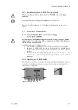
Opening the SIREL SMD
All electrical connections are made with spring-loaded terminals inside the con-
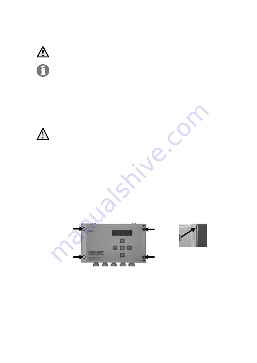
trol unit. To open the control unit, unscrew the four screws underneath the
side covers.
Figure 9
Figure 9: Opening the control unit.
Summary of Contents for DualScat Ex
Page 2: ... SIGRIST PHOTOMETER AG Subject to change without notice 9 2016 ...
Page 6: ...Instruction Manual DualScat Ex iv 10118E 5 ...
Page 53: ...Instruction Manual DualScat Ex 10118E 5 47 ...
Page 54: ...Instruction Manual DualScat Ex 48 10118E 5 11 Appendix ...


