background image

Instruction Manual DualScat Ex 

44 


10118E/5  

8


Packing/Transport 

Wherever possible, use the original packing materials for packing the photome-
ter and its peripheral components. If these materials are no longer available, 
observe the following points: 


Prior to packing, close off the control unit's openings with self-adhesive 
tape or plugs to prevent any packing material from getting into the unit. 


The photometer contains optical and electronic components. Pack the in-
strument in such a way that it will be protected against impact during 
transport. 


Pack all peripherals and accessories separately and mark each one with the 
equipment number (

 Section 1.4). This will prevent mix-ups later on and 

facilitate identification of the components. 

 
If the photometer and control unit are packed this way, they can be dispatched 
with any of the usual means of transport and in any position. 
 

Summary of Contents for DualScat Ex

Page 1: ...Turbidimeter with SIREL SMD Ex SIGRIST PHOTOMETER AG Hofurlistrasse 1 CH 6373 Ennetbürgen Switzerland Phone 41 41 624 54 54 Fax 41 41 624 54 55 E Mail info photometer com Internet www photometer com Document No 10118E Version 5 Valid from SN 450101 ...

Page 2: ... SIGRIST PHOTOMETER AG Subject to change without notice 9 2016 ...

Page 3: ...nts and display SIREL SMD 16 4 2 Control components and display of the SIREL Ex 17 4 3 Normal operation 18 4 4 Service mode 18 4 5 Setting the national language 19 4 6 Setting the measuring range 20 4 7 Setting the relay functions 21 4 8 Setting the limits 23 4 9 Setting the access code 24 4 10 Additional possibilities 25 5 Servicing 26 5 1 Service schedule 26 5 2 Replacement of desiccant in the E...

Page 4: ...Instruction Manual DualScat Ex ii 10118E 5 8 Packing Transport 44 9 Disposal 45 10 Spares 46 11 Appendix 48 12 Index 50 ...

Page 5: ...structions Most import ant functions and complete menu structure 10119E Reference Handbook More sophisticated menu functions and worksteps for advanced users 11766E Data Sheet Descriptions and technical data about the instrument 10120E Service Manual Repair and conversion instructions for ser vice technicians 11044E SIREL Ex Instruction Manual Contains additional information about the SIREL Ex con...

Page 6: ...Instruction Manual DualScat Ex iv 10118E 5 ...

Page 7: ...gle 90 25 single angle 90 single angle 25 1 Control unit standard or Ex version SIREL SMD 100 240 VAC or SIREL SMD 24 VDC SIREL SMD Ex 100 240 VAC or SIREL SMD Ex 24 VDC 1 Housing key square drive for SIREL Ex Only for SIREL Ex 118771 1 Instruction Manual 1 Reference Handbook Brief Instructions Standard scope of supply EX enclosure Product pipe Control unit Example with SIREL SMD Connecting cable ...

Page 8: ...temperature and ambient temperature In line enclosure Various qualities and nominal widths 1 3 Equipment purpose and conformity Incorrect use of the photometer or use for purposes other than the intended duty can produce false measuring results with possible process related dam age or damage to the photometer itself The control unit SIREL SMD and any peripheral components may not be in stalled or ...

Page 9: ...rotec tion level EPL Ga European Directive 2014 34 EU Table 1 Standards The photometer possesses the following certification EC type examination certificate BVS 10 ATEX E 101 X IECEx BVS 16 0054X State of the art engineering practice was followed in the design and manufac ture of the photometer It complies with the generally accepted guidelines with regard to safety and the exercising of due care ...

Page 10: ...er of the con trol unit is indicated on the back The electrical connection data are given on the sticker at the bottom left Figure 2 Labels for the serial number and the electrical connection data on the SIREL SMD Figure 3 Position of the SIGRIST rating plate on the SIREL Ex X Rating plate of the manufac turer SIREL Ex Instruction Manual ...

Page 11: ...wing information Figure 5 Information on identification plate Pos Name 1 Manufacturer 2 Instrument type 3 Serial number 4 Conformity data 5 Ex protection type 6 Temperature classes 7 Ambient tempera ture 8 Certificates 9 Warning You can also consult the photometer s serial number in the menu SYSTEM INFO Reference Handbook ...

Page 12: ...In line housing Varivent or compatible Service voltage 24 VDC of control unit Flow cell borosilicate glass Pyrex or Sapphire stainless steel SS316L 1 4435 seal NBR EPDM FPM or Kalrez Enclosure cast aluminum enclosure GK AlSi 13 Silavont 15 2 component synthetic resin finish Dimensions about 160 mm x Ø200 mm see section 0 for detailed dimension drawing Weight about 6 4 kg Degree of protection IP65 ...

Page 13: ... 24 V with electrical isolation max 50V against earth Relay contacts max 250 VAC max 4 A Digital inputs and outputs max 5 V Service voltage 100 240 V 47 63 Hz or 18 30 VDC 25 W Mains switch None Dimensions 320 mm x 645 mm x 203 mm Detailed dimension drawing see Section 0 Weight Approx 25 kg Protection type IP66 Ambient temperatures 20 C to 50 C Connections See SIREL SMD Additional technical data o...

Page 14: ... This symbol marks energized are as with voltages higher than 48 VAC or 65 VDC where an electric shock haz ard exists In these cases be sure to observe the safety precautions and pro cedures prescribed in the Instruction Manual 2 2 Rules for ensuring safe operation Before starting up the instrument study these rules and be sure to observe them Do not carry out any mechanical or electrical modifica...

Page 15: ...d using a standard in line housing either in hori zontal or vertical product pipes Figure 6 Installation in vertical product pipes Figure 7 Installation in horizontal product pipes Pos Name X Cooling outlet optional Y Make sure the slot points in the direction of flow Z Cooling inlet optional Figure 8 Groove in direction of flow A ...

Page 16: ... in the pipe at a point at least 2 m away from inspection windows or other sources of stray light 3 1 2 Installation of the SIREL SMD Control unit The SIREL SMD and any peripheral devices may not be installed or operated in explosive atmospheres The SIREL SMD can be mounted right on a wall on a mounting grate or on a stand Depending on the cable used cross section the maximum distance between cont...

Page 17: ...on When carrying out electrical installation work always observe the local codes In addition observe the following rules It is absolutely necessary to connect the protective earth conductor Because the SIREL SMD Ex has no mains switch a suitable discon nection device switch plug must be provided close to the mains con nection If malfunctions cannot be eliminated take the instrument out of ser vice...

Page 18: ...unlock the cov er by rotating a quarter turn to the left Square wrench Section 1 2 3 Pull down the cover to open 3 2 4 Establish SIREL SMD Ex electrical connections For information about control signals please refer to Section 2 in the Refer ence Handbook The terminals of the SIREL Ex are located in the lower part of the housing Figure 10 The housing must be open in order to connect the electrical...

Page 19: ...Instruction Manual DualScat Ex 10118E 5 13 Figure 10 Position of SIREL Ex terminals Figure 11 Terminal block for SIREL SMD 100 240 VAC Make up the electrical connections in the following order ...

Page 20: ...ngle instrument 0 4 20 mA max bur den 600 If unused these terminals must be shorted with a jumper 32 33 Reading output for 2nd meas angle 25 read ing in the case of dual angle instrument Provided on dual angle instrument only If unused these terminals must be shorted with a jumper 3 10 17 Control signals for 1st meas angle Reference Handbook 26 31 Control signals for 2nd meas angle Provided on dua...

Page 21: ...epending on instru ment version 3 Set the language spoken in your re gion Section 4 5 Now the menu texts will appear in the desired language 4 Run through a sensor check Section 6 3 If no fault message has appeared the photometer is ready to start measuring 5 Set the measuring range required for your duty conditions Section 4 6 If automatic range switching is de sired standard you can skip this st...

Page 22: ...ween functions in a menu line Change the function values and or change the decimal place of a numerical value in editing mode see below Press simultaneously to return to normal operation Activate the editing mode display shows Enter the setting confirmation Key functions Measuring angle Right arrow key Enter key Up arrow key Reading Unit Current measuring range Down arrow key Left arrow key Second...

Page 23: ...ng the cover 3 Integrated keyboard Figure 13 SIREL Ex control components Figure 14 SIREL Ex Pos Symbols Key functions 1 2 Switch from one menu line to another Switch from numerical data to editing mode see below 4 5 Switch between functions in a menu line Change the function values and or change the decimal place of a numerical value in editing mode see below 4 5 Press simultaneously to return to ...

Page 24: ...ion has occurred try to pinpoint the mal function Section 6 Table 2 Display examples and what they mean To display the extremes of the measuring range currently set press one of the keys or No other action need be taken at the control unit for normal op eration 4 4 Service mode The photometer is configured in the service mode Normal measuring operation is interrupted and a guidance menu appears on...

Page 25: ...ference Handbook 4 5 Setting the national language Set your national language for the menus and messages this way Action Display Example Remarks 1 Zugriffscode 00000 If no individual access code was set proceed to step 3 2 Enter code change number change place Zugriffscode Enter your own access code here 3 SENSOR CHECK Instrument in service mode 4 4 x KONFIGURIEREN 5 Sprache Deutsch 6 Sprache Deut...

Page 26: ...ple Remarks 1 Access code 00000 If no individual access code was set proceed to step 3 2 Enter code change number change place Access code Enter your own access code here 3 SENSOR CHECK Instrument in service mode 4 2 x MEAS RANGE LIMITS 5 Select meas angle 1st meas angle 2nd meas angle Meas range xx Automatic 6 Meas range xx Automatic Activate editing mode 7 Select meas range Meas range xx Table 3...

Page 27: ...ay functions The control unit has two relay outputs Section 3 2 the functions of which are freely configurable Several functions can be assigned to a given relay sim ultaneously The relay in question is activated whenever one of the configured functions becomes active OR link Action Display Example Remarks 1 Access code 00000 If no individual access code was set proceed to step 3 2 Enter code chan...

Page 28: ... selection 9 Relay 2 li AL se ch in Configure relay 2 10 Relay 2 li AL se ch in Activate editing mode 11 Assign functions function on off change function Relay 2 LI AL se ch in li limit 2 exceeded al alarm fault oc curred se instrument in ser vice mode ch sensor check run ning in relay inverted Functions written in CAPITALS are activated e g LI 12 Relay 2 li AL se ch in Confirm selection 13 simult...

Page 29: ...lim it s lim it p a ssiv e lim it a ctive t t re a d in g Figure 15 Upper and lower thresholds of a limit One or two limits are available only if the relays are programmed accordingly Section 4 7 Action Display Example Remarks 1 Access code 00000 If no individual access code was set proceed to step 3 2 Enter code change number change place Access code Enter your own access code here 3 SENSOR CHECK...

Page 30: ... procedure for 2nd limit steps 6 to 16 18 simultaneous 90 2 23 NTU 5 Instrument in normal oper ation 4 9 Setting the access code You can set your own access code to protect your DualScat Ex settings against unauthorized manipulation Action Display Example Remarks 1 Access code 00000 If no individual access code was set proceed to step 3 2 Enter code change number change place Access code Enter you...

Page 31: ...ntation describes only those options that are required for initial start up and normal operation of the instrument Many other parameters are available to enable you to adapt the DualScat Ex perfectly to your specific duty requirements Just to mention a couple You can alter the behavior of the reading outputs or you can test the instrument in the manual mode Consult the Reference Handbook supplied ...

Page 32: ... for sus taining proper operation Once a year or as needed User Recalibrate the photometer Section 5 6 Advisable for maintaining de tection accuracy Interval de pends on medium Every 2 years Service or ganization Replace seals Absolutely essential for sus taining proper operation Every 5 years or as needed Service or ganization Replace the flow cell windows Advisable for maintaining de tection acc...

Page 33: ... then the enclosure 5 Remove the desiccant and dispose of it as directed in the disposal table in Section 9 6 Remove the new desiccant from it protec tive pouch and insert it as shown in the ad jacent illustration Spares Section 10 Press the desiccant all the way into the holder so that it cannot come into contact with the enclosure Reclose the enclosure immediately to prevent the desiccant from a...

Page 34: ...ver open the photometer when cold product is flowing through the pipes Try to do this work during a sterilization phase or when the product is at least at room temperature The desiccant in the sensor head can be replaced during normal operation Action 1 Disconnect the power supply to the control unit 2 Wait 10 minutes before continuing Allows instrument to cool to a safe temperature level and resi...

Page 35: ...first 7 Remove the moisture indicator by unscrew ing the two screws A then install the new indicator 8 Clean the optics with a cotton rag entire surface see arrow 9 Reattach the desiccant holder using the two screws i e step 5 in reverse and reassem ble the unit with the sensor head 10 Loosen hex head screw on the sensor head to allow excess air to escape A A A A ...

Page 36: ...he service conditions and the medium the extent of fouling may become too great to be compen sated Action 1 Make sure the product pipe is empty 2 Disconnect the power supply to the control unit 3 Remove the photometer from the product pipe 4 Clean the sensor head including the glass ar row with an acidic nonabrasive cleaning agent and a soft lint free rag Do not use any other cleaning methods or c...

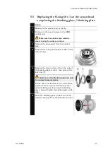
Page 37: ... photometer from the product pipe 4 Remove the O ring and replace it with a new clean O ring 5 Remove the closure clamp X on the side of the blanking glass or plate then remove the lock ring Y Scratches on the blanking glass can lead to incorrect measurements Ensure that no scratches occur on the black ened outer face and uncoloured inner face when installing and removing the blanking glass Always...

Page 38: ...ass or plate and fasten it with the closure clamp 10 Reattach the photometer in the product pipe 11 Restore the power supply to the SIREL con trol unit 5 6 Recalibrating the photometer Recalibration of the photometer can cause the readings to differ from the pre vious ones because the instrument is readjusted to a fixed reference standard Recalibration can be carried out in either of two ways Reca...

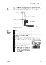
Page 39: ...emove the calibration unit supplied with the instrument from its box Clean the calibration unit inside and out with a soft lint free rag Make sure the serial number printed on the calibration unit matches with the instrument serial number 4 Set the checking unit vertically on a flat sur face Align the photometer so that the groove on the sensor head mates with the guide pin on the checking unit Be...

Page 40: ...ut half full of water B Make sure no bubbles are created when the water flows into the checking unit so that no troublesome bubbles occur inside it 9 Carry out the recalibration on the control unit as directed in Section 5 6 3 The nominal value s are printed on the checking unit 10 Drain the checking unit remove the photom eter and replace it in your product pipe Section 3 1 11 Restart the instrum...

Page 41: ...moved in this case Figure 16 Figure 17 Test setup for formazine recalibration Action 1 From a formazine stock solution prepare a dilu tion of 6 8 NTU calibration suspension You will find a recipe for producing the formazine stock solution in the Reference Handbook The more accurately you know the value of the calibration suspension the more precisely you will be able to recalibrate the instrument ...

Page 42: ...ove the photometer and replace it in your product pipe Section 3 1 11 Restart the instrument in normal operation 5 6 3 Recalibration procedure The recalibration itself is carried out on the control unit Action Display Example Remarks 1 Access code 00000 If no individual access code was set proceed to step 3 2 Enter code change number change place Access code Enter your own access code here 3 SENSO...

Page 43: ...nal values no recalibration is necessary proceed to Point 18 13 Adju Retain 14 Adju Retain 15 Adju Adapt 16 Adju running Compute the calibration factors 17 Wait until the DualScat Ex has computed the calibration factors and the display changes Meas90 Meas25 34 5 3 50 Display of the rough ref erence values without de tected value corrections If outside tolerance ap pears on the display the nominal ...

Page 44: ...e displayed Analyze the fault message Section 6 2 Reading is very suspect Check whether the medium in the product pipe still meets the normal duty conditions Section 1 5 Carry out a sensor check Section 6 3 Check whether the photometer is properly in stalled Section 3 1 Check whether the service work has been car ried out according to the Service Schedule Section 5 1 Check the dry chamber in the E...

Page 45: ...ctive Service technician Remove the photometer from the product pipe immedi ately to prevent flooding of the sensor head Light source The detectors are not receiving any light Turbidity excessively high 2000 NTU in the product pipe Severely fouled sensor head Section 5 4 Defective light source Service technician Measurement The detectors are re ceiving too much light Photometer not installed in th...

Page 46: ...he sensor check is an internal photometer plausibility check that with the factory setting is carried out automatically once a day The checking interval can be changed without restriction or switched off entirely Irrespective of this automatic mode the sensor check can be initiated at any time either manually or by means of external control signals Reference Handbook Action Display Example Remarks...

Page 47: ...appy to give you address You will also find a current list of all SIGRIST country representatives on the Internet at www photometer com Whenever you contact a SIGRIST service organization or Customer Service in Switzerland please be sure to have the following information at hand The serial number of the control unit Section 1 4 A description of the instrument s behavior and the worksteps being car...

Page 48: ...07 F08 F09 F10 System faults S01 S02 S03 S04 S05 Recalibration Recal 1 Recal 2 Recal 3 Recal 4 Recal 5 Recal 6 LED temperature LED temp Max temperature in the Ex enclosure Max temp Calibration factors Moni meas 90 Moni meas 25 Moisture level Moisture level Adjustment values Val Adjust 90 Val Adjust 25 ...

Page 49: ...se deposits should remain inside 5 Check the photometer s dry chamber and if necessary replace the desic cant Section 5 2 6 Demount the control unit 7 Make sure all covers and hoods for the photometer and control unit and all closures on them are properly locked No particular conditions are required for storage of the equipment but do ob serve the following points Because the photometer and contro...

Page 50: ...to prevent any packing material from getting into the unit The photometer contains optical and electronic components Pack the in strument in such a way that it will be protected against impact during transport Pack all peripherals and accessories separately and mark each one with the equipment number Section 1 4 This will prevent mix ups later on and facilitate identification of the components If ...

Page 51: ...e their materials according to the following table Category Materials Disposal possibilities Packing Cardboard wood paper Reuse as packing material local disposal points incinerator Plastic sheet polystyrene shells Reuse as packing material recy cling Electronics Printed circuit boards elec tromechanical components Disposal as electronic scrap Optics Glass aluminum brass Recycling via scrap glass ...

Page 52: ...ontrol unit SIREL SMD 24VDC 119083 Control unit SIREL SMD EX 100 240 VAC Ex version 24VDC is available too observe service voltage 108157 Cover with membrane keypad for SIREL 118771 Housing key square drive for SIREL Ex only for SIREL Ex 119125 Blanking glass coated with PVD chrome with EPDM O Ring Section 5 5 118786 Blanking plate sand blasted with EPDM O Ring Section 5 5 108247 O Ring EPDM 60x3 ...

Page 53: ...Instruction Manual DualScat Ex 10118E 5 47 ...

Page 54: ...Instruction Manual DualScat Ex 48 10118E 5 11 Appendix ...

Page 55: ...Instruction Manual DualScat Ex 10118E 5 49 ...

Page 56: ...ault message 38 39 formazine calibration 35 fouling 30 G general view 1 guidelines 3 H horizontal 9 I initial start up 15 in line housing 9 inspection windows 10 installation 9 instrument number 4 Internet 41 K key functions SIREL Ex 17 L labels identification 4 language setting 19 light source fault 39 limits definition 23 limits setting 23 LVG 3 M malfunction pinpointing causes 38 measurement fa...

Page 57: ...sorCheck fault 39 service mode 18 service organization 41 service schedule 26 servicing work 26 solid reference 33 35 spare parts 46 standards 3 start up 15 symbols iii 8 systemfault 40 T technical data 6 temperature fault 40 terminal block 13 tightness 28 30 transport means 44 V Varivent 6 vertical 9 voltage 8 W warning 8 Z zone Ex 2 ...

Page 58: ...SIGRIST PHOTOMETER AG Hofurlistrasse 1 CH 6373 Ennetbürgen Switzerland Tel 41 41 624 54 54 Fax 41 41 624 54 55 info photometer com www photometer com ...

Reviews: