background image

Instruction Manual OilGuard 2 W 

Mounting 

24 

14809E/2 

The following procedure describes how to mount the sample connections on the  
OilGuard 2 W: 


WORKSTEP 

ADDITIONAL INFO / IMAGES 

1. 

Remove the optics unit according to  
Section 9.1.1 and fasten on the docking sta-
tion. 


 Warning! UV radiation. 

Use UV goggles and gloves. 


2. 

Fasten the inlet hose on the inlet pipe  
(Figure 3, pos. 1). 


3. 

Fasten the outlet hose on the outlet pipe 
(Figure 3, pos. 7). 

When doing so, press the outlet cone  
(Figure 3, pos. 5) downward by hand so that 
the outlet pipe (Figure 3, pos. 7) is not pressed 
into the measuring cell space. 


 Flooding of the measuring cell 

due to improper mounting of the 
outlet hose. 

The outlet hose must be fastened 
so that the holes on the side are 
not covered (flood protection). 
Section 4.4.1  


4. 

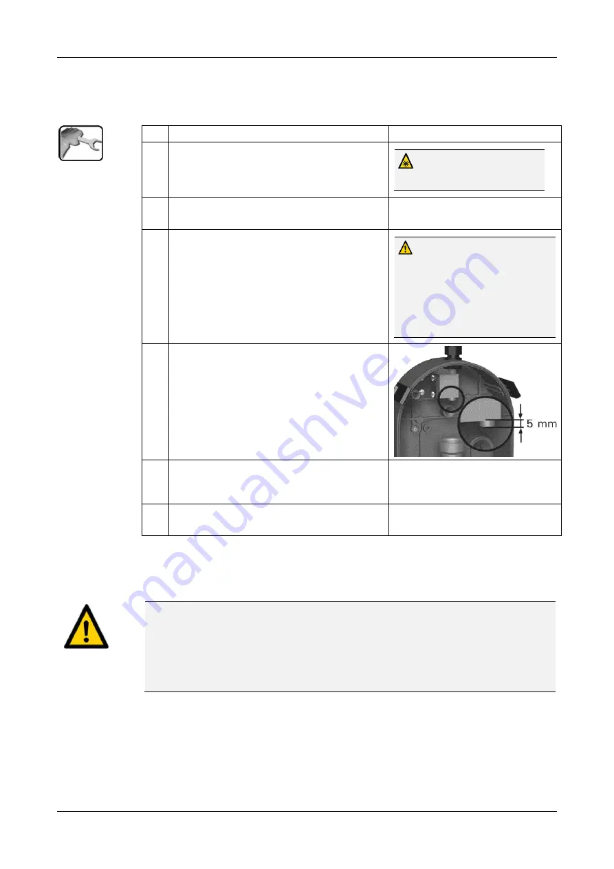
Check to ensure the inlet pipe (Figure 3,  
pos. 1) projects 5 mm out of the holder. 


5. 

Check to ensure the outlet cone (Figure 3, pos. 
5) is in contact with the conduit gland 
(Figure 3, pos. 6). 


6. 

Place the optics unit back on the measuring 
cell unit and lock with the four mounting clips. 


4.5


Mounting the optional accessories 


4.5.1


General information on the optional accessories 


CAUTION! 

Note the following when mounting the optional accessories: 


All hose connections must be secured with hose clamps. The connections should be 
checked about two weeks after installation to ensure that no air can be pulled in. 


A minimum flow of 1 l/min. must be guaranteed on the overflow of the level control. 


The dimensions on the dimension sheets must be adhered to (course and radii of the 
hoses, spacing etc.). 


4.5.2


Mounting the level control 

Mounting of the level control is made according to the dimension sheets  

OILGUARD 2 W/1-MB


Summary of Contents for OilGuard 2 W

Page 1: ...Document number 14809E Version 2 Valid from S N 625020 SW V129 INSTRUCTION MANUAL OilGuard 2 W Oil trace monitor with free fall measuring cell ...

Page 2: ...ST PHOTOMETER AG subject to technical changes without notice 2 2019 SIGRIST PHOTOMETER AG Hofurlistrasse 1 CH 6373 Ennetbürgen Switzerland Tel 41 41 624 54 54 Fax 41 41 624 54 55 info photometer com www photometer com ...

Page 3: ...7 3 1 Dangers when properly used 17 3 2 Danger due to UV radiation 18 3 3 Residual risk 18 3 4 Warning and danger symbols on the instrument 18 3 5 Preventing undesirable online access attempts 19 4 Mounting 20 4 1 Location selection 20 4 2 Mounting the OilGuard 2 W 20 4 3 Mounting the docking station 21 4 4 Mounting the sample connections 22 4 4 1 General information on the sample connections 22 4...

Page 4: ... 51 8 3 1 Upper and lower threshold value of a limit 52 8 3 2 Reading if limit exceeded or undershot 52 8 4 Setting the outputs digital 53 8 5 Setting the date and time 54 8 6 Setting or changing the access code 55 8 7 Backup configured data 56 9 Servicing 57 9 1 Servicing schedule for OilGuard 2 W 57 9 1 1 Fastening the optics unit to the docking station 58 9 1 2 Checking the flow rate and cleanl...

Page 5: ...Contents Instruction Manual OilGuard 2 W 14809E 2 5 14 Disposal 79 15 Spare parts list 80 15 1 Spare parts for the OilGuard 2 W 80 16 Index 81 Makro ...

Page 6: ...Instruction Manual OilGuard 2 W Contents 6 14809E 2 This page is intentionally blank Makro ...

Page 7: ...TENT 14808E Brief Instructions The most important functions and the servicing schedule 14811E Reference Manual More sophisticated menu functions and worksteps for advanced users 14790E Data Sheet Descriptions and technical data about the instru ment 14813E Service Manual Repair and conversion instructions for service engi neers 14897DEF Declaration of Con formity Compliance with the underlying dir...

Page 8: ...onnel who have read and un derstood the content of the Instruction Manual 1 10 Declaration of conformity Current technological principles were followed in designing and manufacturing the instru ment They comply with the applicable guidelines concerning safety and duty to take due care EU The measuring instrument meets all applicable requirements within the European Union EU for carrying the CE mar...

Page 9: ...roper changes to the instrument have been performed The instrument has not been operated within the specifications in particular concerning pressure and temperature The instrument is exposed to vibrations shocks or other mechanical forces 1 13 Meaning of the safety symbols All danger symbols used in this document are explained below DANGER Danger due to electrical shock that may result in serious ...

Page 10: ...RFACES Danger due to hot surfaces that may result in injuries Non observance of this warning can lead to burns 1 14 Meaning of the pictograms All pictograms used in this document are explained below Additional information about the current topic Practical procedures when working with the OilGuard 2 W Manipulations on the touchscreen The screenshot is an example and may differ from current device ...

Page 11: ...trument overview 2 1 Overview of the OilGuard 2 W Figure 1 Measuring point with optional accessories Photometer with free fall measur ing cell Outlet Sample inlet of the level control Sample overflow of the level control Set for wall mounting Inlet pipe on the photometer ...

Page 12: ...e photometer The photometer is fitted with the following rating plate Figure 2 Rating plate on OilGuard 2 W Manufacturer Country of origin Product name Serial number Date of manufacture Service voltage Frequency range Power Observe the disposal information Observe the Instruction Manual ...

Page 13: ...rd 2 W with set for wall mounting and lev el control 121316 OilGuard 2 W A with set for wall mounting and lev el control With automatic ad justment 121210 OilGuard 2 W 121315 OilGuard 2 W A With automatic ad justment Documentation PCS ART NO NAME VIEW VARIANT 1 14809 Instruction Manual German French English 1 14811 Reference Manual German English 1 14808 Brief Instructions German French English ...

Page 14: ...the OilGuard 2 W 1 121255 Checking unit for OilGuard 2 W Manual calibration unit 1 119102 Profibus DP inter faces print 1 119103 Modbus RTU in terfaces print 1 121120 Profinet IO interfaces print 1 119798 HART interfaces print 1 119041 4 way current output module 1 119082 I O module 1 119045 24 VDC power supply 20 W IP66 input 100 to 240 VAC 1 119081 Ethernet cable IP66 for fixed installa tion ...

Page 15: ...ower consumption 8 W Dimensions See detailed dimensional drawing Weight 3 2 kg Protection class IP54 only electronics Maximum operating alti tude 2 000 m above sea level for instruments that are not operated with low voltage mains relays Ambient temperature 0 50 C Ambient humidity 0 95 rel humidity non condensing Housing Plastic ABS Outputs inputs Outputs 2 x 0 4 20 mA galvanically isolated up to ...

Page 16: ...aterial Inlet pipe stainless steel 1 4435 or PVC Outlet PVC Sample pressure Pressureless Medium temperature 0 40 C not more than 30 C over the ambient temperature Sample flow 2 5 7 l min Connections Inlet pipe 12 mm Outlet pipe 25 mm 24 VDC power supply Values Service voltage 100 240 VAC 47 63 Hz Power consumption Max 25 W the power consumption of the connected sensors must not exceed 21 W Maximum...

Page 17: ...instrument changes hands Operating the instrument without knowledge of the Instruction Manual may lead to injuries to persons and damage to the instrument If the instrument changes hands always include the Instruction Manual If the Instruction Manual is lost you can request a replacement Registered users can download the current version at www photometer com CAUTION Escaping water from leaks on th...

Page 18: ...e LED out of operation when the housing is open Switch off the OilGuard when carrying out servicing duties or wear UV goggles and gloves 3 3 Residual risk WARNING According to the risk assessment of the applied safety directive DIN EN 61010 1 there remains the risk of the displayed measuring values being incorrect This risk can be reduced with the following measures Use an access code to prevent u...

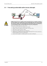
Page 19: ... then any Internet us er can in principle access your instrument and change the configuration Please note the following points to prevent this Never connect the instrument directly to the Internet Operate it behind a firewall and block access to the instrument Only connect to branch offices via VPN Change the standard password on commissioning Always keep up to date with the latest changes regardi...

Page 20: ...nt can be skewed by excessive external light 4 2 Mounting the OilGuard 2 W The dimensional specifications according to the mounting drawings attached in the docu mentation ring binder of OilGuard 2 W Mount the OilGuard 2 W as follows WORKSTEP ADDITIONAL INFO IMAGES 1 Screw on the mounting bracket at the desired position The mounting bracket must be hori zontally aligned with a spirit level 2 Align...

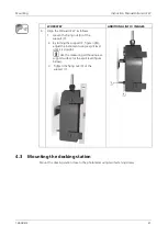
Page 21: ... support Y 2 By turning the support Y figure right adjust the instrument using a spirit level until it is straight Use the measuring cell housing as a support surface for the spirit level figure below 3 Tighten the fixing nut X of the support Y 4 3 Mounting the docking station Mount the docking station close to the photometer using two fastening screws ...

Page 22: ...secured with hose clamps The connections should be checked about two weeks after installation to ensure that no air can be pulled in In order to ensure an accurate measurement of the oil concentration observe the following points when mounting the sample connections A continuous water flow rate as specified in the Section 2 4 is required In all cases a regulator valve or level control is necessary...

Page 23: ... 4 4 2 Fastening the sample connections on the OilGuard 2 W Figure 3 Overview of the measuring cell unit Inlet pipe Conduit gland for inlet pipe Holder for inlet pipe Light trap Outlet cone Conduit gland for outlet pipe Outlet pipe with flood protection ...

Page 24: ... flood protection Section 4 4 1 4 Check to ensure the inlet pipe Figure 3 pos 1 projects 5 mm out of the holder 5 Check to ensure the outlet cone Figure 3 pos 5 is in contact with the conduit gland Figure 3 pos 6 6 Place the optics unit back on the measuring cell unit and lock with the four mounting clips 4 5 Mounting the optional accessories 4 5 1 General information on the optional accessories C...

Page 25: ...e the system has no main switch a suitable disconnection device switch plug should be installed near the service voltage It must be designated and easily accessible It is imperative that the protective conductor is connected The system must not be charged with voltage until the installation is completed and all covers are mounted On systems with a service voltage of between 100 and 240 VAC a back ...

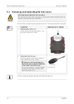
Page 26: ...wing describes this process WORKSTEP ADDITIONAL INFO IMAGES 1 Removing the front cover Loosen the five screws circles with a 7 mm key and remove the front cover 2 Attaching the front cover Carefully mount the front cover and fasten in place with the five screws circles Damage to the threaded inserts in the housing due to excessive tightening of the screws on the front cover Use a hex key without a...

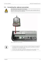
Page 27: ...ectrical connections have been established Figure 4 Position of the customer terminals The cables should be long enough so that there is sufficient freedom of movement for the photometer and its peripherals when carrying out servicing duties e g fastening the photometer onto the docking station The three larger cable glands are designed for cables with an outer diameter of 4 to 8 mm while the smal...

Page 28: ...tions in the following sequence TERMINALS MEANING REMARKS 1 1 2 3 Output 1 relay contact 1 The relay contacts can be freely con figured 2 4 5 6 Output 2 relay contact 2 3 18 19 Current output 1 0 4 20 mA 4 20 21 Current output 2 0 4 20 mA 5 22 23 Connection for optional flow rate monitoring Use the small cable gland X 6 7 8 9 18 30 VDC power supply Use the cable gland Y in the mid dle ...

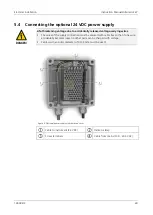
Page 29: ...ed voltage carrying wires The wires of the supply connection must be secured with cable ties so that if one wire accidentally becomes loose no other parts can be charged with voltage Cables with an outer diameter of 4 to 8 mm must be used Figure 5 Optional power supply with removed cover Cable to instrument 24 VDC Indicator lamp Screw terminals Cable from mains 100 240 VAC ...

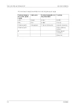
Page 30: ...ting the power supply Terminal designa tion in the power supply Cable color Terminal designation in the photometer Function 24 V Brown 8 24 V 24 VDC RTN Blue 9 GND Ground Protective earth Yellow green 7 Ground connection Ground connection Protective earth Mains protective ground N Mains neutral conductor L Mains live ...

Page 31: ...e Handbook 5 5 1 Overview of Modbus RTU and Profibus DP Figure 6 Overview of field bus interfaces Field bus interface connection printed circuit board for Profibus DP Field bus interface connection printed circuit board for Modbus RTU Profibus DP terminals Modbus RTU terminals DIL switch for matching resistors Switches 1 and 2 must be ON DIL switch for matching resistors Switches 1 and 2 must be O...

Page 32: ...integrated in the Oil Guard 2 W The module has an internal switch and provides two Ethernet ports The cable is connected directly to the RJ45 plug of the Profinet IO module inside the in strument or via external M12 connectors When connecting directly to the RJ45 plug please note that only plugs with a short and flat design can be used In the Digi interf General menu the Modul type must be set to ...

Page 33: ...ART Serves as interface to HART HART terminals 5 5 5 Connecting to HART The terminals of the HART module are configured as follows Terminals HART Functional description 1 mA In Must be connected with terminal 13 mA 1 of SICON M 2 mA In Must be connected with terminal 12 mA 1 of SICON M 3 Shield Cable shielding 4 mA Out Current output 1 with HART 5 mA Out Current output 1 with HART The loop resista...

Page 34: ...re 9 Overview of the 4 way current output module 4 way current output Terminals 5 6 2 Connecting the 4 way current output The terminals of the 4 way current output are configured as follows Terminals 4 way current output Functional description 1 mA 5 Current output 5 2 mA 5 3 mA 6 Current output 6 4 mA 6 5 mA 7 Current output 7 6 mA 7 7 mA 8 Current output 8 8 mA 8 The burden on the current output...

Page 35: ...the sampling system for the correct sample feed and then open the sample feed Section 4 4 Flooding of the measur ing instrument due to im proper mounting of the out let hose The outlet hose must be fas tened so that the holes on the side are not covered flood pro tection 3 Check the flow rate and ensure that the light trap and shutter are clean There must be no pressure surge when turning the wate...

Page 36: ...ish Accord ingly the displayed language during the initial start up is English 6 2 The instrument carries out an internal func tional check 6 3 The instrument is ready for measurement 7 Set the operating language Section 8 1 8 Set the current outputs Section 8 2 9 Set the limits Section 8 3 10 Set outputs 1 2 relay outputs Section 8 4 11 Set the date and time Section 8 5 12 Enter the access code S...

Page 37: ...cribed in detail in the Reference Manual The instrument has a touchscreen It is operated by touching with your finger The navi gation elements change color when touched CAUTION Sensitive touchscreen The touch screen can be damaged through improper handling Damage can be avoided with the following measures Touch the touchscreen only with your fingers and not with sharp objects Use only slight press...

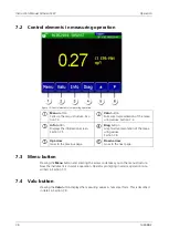
Page 38: ...on screen Section 7 5 Diag button Graphical representation of the meas uring values Section 7 6 Up arrow Goes to the previous page Down arrow Goes to the next page 7 3 Menu button Pressing the Menu button and entering the access code takes you to the menu structure Now the instrument is in service operation Operator prompting in service operation is de scribed in Section 7 11 7 4 Valu button Press...

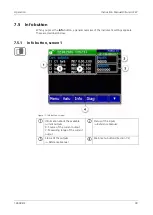
Page 39: ...rument settings appears These are described below 7 5 1 Info button screen 1 Figure 11 Info button screen 1 Information about the available current outputs X Source of the current output Y Measuring range of the current output Status of the inputs Reference Manual Status of the outputs Reference Manual Main menu buttons Section 7 2 ...

Page 40: ...Instruction Manual OilGuard 2 W Operation 40 14809E 2 7 5 2 Page 2 Info button Figure 12 Info screen page 2 Contact information Display of up to 5 pending fault mes sages ...

Page 41: ...ues The measuring values can be record ed from 3 minutes to 32 days and graphically represented The color of the measuring value curves corresponds to the measuring channels on the right side of the dis play position 3 Main menu buttons The logger functions Log button are described in the Section 7 7 Measuring channels Numerical representation of the set measuring channels Current measured value e...

Page 42: ...llowing screen appears Figure 14 Functions of the Log display The cursor shows the time position which is represented at pos 4 The cursor position can be changed ei ther by briefly touching with your fingertip or by pressing the buttons Represented time period The following time ranges can be set 3 min 15 min 1 hour 3 hours 9 hours 1 day 3 days 10 days 32 days The red bar indicates how much of the...

Page 43: ...If faults should occur warning and fault messages are shown here and the status line changes to orange or red Interface information Top left Logger status Top right Modbus HART Profinet or Profibus status Below Ethernet IP status The following messages are possible IP not connected cable not connected IP DHCP running IP 169 254 1 1 example address Color coding Black Not active not present Blue Act...

Page 44: ...09E 2 7 9 Lock unlock the touch screen MANIPULATION 1 Press the lock icon top left 2 Within one second press the key bottom at the outside right Depending on the initial state the lock icon changes as follows Touch screen unlocked Touch screen locked ...

Page 45: ...The following applies in service operation The measuring values remain on the last values on the digital interfaces Depending on the configuration the current outputs go to 0 4 mA or remain on the last measuring values The limits are deactivated If an output for service is programmed it is activated Fault messages are suppressed This does not apply when the Current outputs General For service para...

Page 46: ...e mode Path specification Page number total number of pages Main menus Instrument specific menus of the photometer Next page Meas button The instrument changes to measuring operation Menu button The display goes back to mean menus and remains in service mode ESC button The display goes back one level in the menu hierarchy until the measuring mode finally is reached ...

Page 47: ...Enter value 2 Select SI prefix Function n 10 9 u 10 6 m 10 3 k 103 M 106 G 109 Numerical entry Deletes one digit of the dis played value C Clears the displayed value ESC Touching the ESC field causes the display to go back one level in the menu hierarchy The entered value is not saved OK Confirm entered value If the value entry is too high or too low a white arrow appears in a red field top right ...

Page 48: ...ssing a selection item saves the configuration and completes the entry Figure 18 Example of single selection 7 11 4 Multiple selection of functions The multiple selection is identifiable by the OK button bottom right The currently selected values are green Use the Up Down arrows to navigate the options in long lists Pressing a selection item changes the active status of the corresponding item Pres...

Page 49: ...ory setting is 0 3 Press the Configuration button to access lan guage selection If the desired menu does not appear press the arrow bottom right 4 Press language field circle The list of all lan guages appears factory setting is English 5 Apply the desired language by pressing the corresponding field or press the ESC button to cancel 6 Press the Meas button The instrument is in measuring op eratio...

Page 50: ... Factory setting is 0 3 Press the Curr outputs button If the desired menu does not appear press the arrow at the bot tom right 4 Select between C1 n 5 Select the source The following selection is available C1 measuring channel A1 n analog channels 6 Select the Range MR1 MR8 In 1 In 2 Auto 1 Auto 2 Reference Manual 7 Press the Meas button The instrument is in measuring op eration again ...

Page 51: ...he bot tom right 4 Select between L1 n 5 Select the Source The following selection is available when present C1 measuring channel A1 n analog channels 6 Define the Mode The following selection is available Inactive limit monitoring of this channel is deactivated Exceeded limit active when the set threshold value is ex ceeded Undershot limit active when the set threshold value is under shot 7 Defin...

Page 52: ...active until the upper threshold value is again ex ceeded Figure 20 Diagram of limit exceeded Measuring value Upper threshold value Lower threshold value Time Limit active Limit passive 8 3 2 Reading if limit exceeded or undershot If a limit event occurs during operation it has the fol lowing effects on measuring operation Threshold value display indicates an unusual state If an output for the cor...

Page 53: ...tting is 0 3 Press the Inp outputs button If the desired menu does not appear press the arrow at the bot tom right 4 Press the Outputs button 5 Select the O1 Inactive O Inactive output 6 Activate the outputs multiple selection possible Activated outputs are highlighted green Invert Inverts the outputs Prio fault Fault Warning Service Adjustment Limit 1 n The other buttons named MR Out are for auto...

Page 54: ...ttom right 4 To enter the time press the currently displayed time at the Time menu item and enter the new time with the number pad Confirm entry with OK The time must be entered in the format hh mm ss 5 To enter the date press the currently displayed date at the Date menu item and enter the new date with the number pad Confirm entry with OK The date must be entered in the format selected under the...

Page 55: ... button 2 Set the access code and confirm with OK Factory setting is 0 3 Press the Configuration button If the desired menu does not appear press the arrow bottom right 4 Press the button to the right of the Access code description text 5 Enter the access code and confirm with OK 6 Press the Meas button The instrument is in measuring op eration again A forgotten access code can be cleared only by ...

Page 56: ...et the access code and confirm with OK Factory setting is 0 3 Press the System info button If the desired menu does not appear press the arrow bottom right 4 In the User SD and Expert SD submenus press the Copy function The user and expert data are copied to the microSD card After a suc cessfully completed procedure acknowledge with the OK button 5 Press the Meas button The instrument is in measur...

Page 57: ...as needed Operator Performing adjustment Section 9 1 3 Section 9 1 4 Obligatory measure for main taining measuring accuracy Cleaning parts which come into contact with water Section 9 1 5 Annually or as needed Operator Replacing the air filter Section 9 1 6 Obligatory measure for main taining functional efficiency Every 10 years or as needed Operator Replacing the battery Section 9 1 7 Obligatory ...

Page 58: ...s and skin The UV LED is only accessible when the housing is open The OilGuard 2 W is equipped with an automatic cut off device that puts the LED out of operation when the housing is open Switch off the OilGuard 2 W when carrying out servicing duties or wear UV goggles and gloves Figure 21 Optics unit fastened to docking station Measuring cell unit Optics unit Docking station Knurled screw for fas...

Page 59: ... same time lift the mounting clip figure 2 Press the mounting clip in the direction of the arrow over the lock plate of the optics unit figure 3 and then open figure 4 Position of the mounting clips Figure 1 Figure 2 Figure 3 Figure 4 2 Remove the optics unit Figure 21 pos 2 from the measuring cell unit Figure 21 pos 1 and position it on the docking station Figure 21 pos 3 Pay attention to the mil...

Page 60: ...o Section 9 1 1 and fasten on the docking station Danger due to UV radia tion Use UV goggles and gloves 2 Check the flow rate of the sample according to the technical data Section 2 4 3 Check the water jet Normal jet reflections are visible in the water jet Uneven water jet after water stop Too little water Too much water With large air bubbles 4 Check the light trap in the measuring cell for resi...

Page 61: ...ORKSTEP ADDITIONAL INFO IMAGES 5 Check the shutter assembly for residual water circle Remove any residues with a cloth 6 Place the optics unit back on the measuring cell unit and lock with the four mounting clips Pay attention to the guide pins see figu re ...

Page 62: ...inlet pipe Y 3 Remove the optics unit on the photometer according to Section 9 1 1 and fasten on the docking station Danger UV radiation Use UV goggles and gloves 4 Inspect the checking unit to ensure it is clean The checking unit must have the same temperature as the in strument If the checking unit is stored in another room let the unit acclimatize to the conditions 5 Mount the checking unit and...

Page 63: ...adjustment was not successful it is in dicated with Adjust fault In this case check the points in the following list one after the other Cleanliness of the checking unit Correct checking unit used Nominal value corresponds to the value of the checking unit Large temperature difference between the OilGuard 2 W and the checking unit Soiled optics in the instrument In this case contact customer servi...

Page 64: ...he photometer to service operation Section 7 10 2 Press the Recalibration button and then C1 EPA PAH 3 Carry out the adjustment as follows Press the initiate button This starts the ad justment If the adjustment was successful this is con firmed with Adjustment OK This completes the adjustment If the calibration check was not successful it is indicated with Adjust fault A possible cause of this is ...

Page 65: ...ter WORKSTEP ADDITIONAL INFO IMAGES 1 Interrupt the sample supply to the photome ter Section 4 4 2 Remove the inlet and outlet from the pho tometer 3 Remove the optics unit on the photometer according to Section 9 1 1 and fasten on the docking station Danger UV radiation Use UV goggles and gloves 4 Loosen the conduit gland A and remove the inlet pipe B 5 Remove the outlet cone C by pulling it up w...

Page 66: ...ary When doing so also inspect the seal in the outlet cone arrow 8 Insert the outlet pipe into the conduit gland up to the stop and fasten loosely in place The outlet pipe should protrude approx 20 mm into the measuring cell unit 9 Put the outlet cone C onto the outlet pipe E up to the stop When doing so hold the outlet pipe from below Now press the outlet cone together with the outlet pipe downwa...

Page 67: ... space between the outlet cone and the conduit gland 11 Insert the inlet pipe B from above into the conduit gland A up to the stop 12 Tighten the inlet pipe B with the conduit gland A The inlet pipe should protrude 5 mm out of the holder 13 Place the optics unit back on the measuring cell unit and lock with the four mounting clips Pay attention to the guide pins see figure ...

Page 68: ... the optics unit on the photometer according to Section 9 1 1and fasten on the docking station Danger UV radiation Use UV goggles and gloves 4 Remove the two screws arrows then the fil ter cover B and filter A 5 Insert the new filter A in the housing and fasten the filter cover B in place with the two screws D and washers C A Filter B Filter cover C Washer D Screw 6 Place the optics unit back on t...

Page 69: ...ument is disconnected Before opening the instrument make sure that no connected lines are charged with voltage The following describes the replacement of the battery WORKSTEP ADDITIONAL INFO IMAGES 1 Interrupt the service voltage to the photome ter Section 5 2 Loosen the five screws circles with a 7 mm key and remove the cover 7 mm hex key 3 Remove the old battery and replace with a new one circle...

Page 70: ...h the five screws Damage to the threaded inserts in the housing due to excessive tightening of the screws on the cover Use a hex key without a T handle to tighten the screws of the cover finger tight tighten ing torque 1 Nm 7 mm hex key 5 Put the instrument into operation again 6 Set the date and time as described in Section 8 5 ...

Page 71: ...4 The reading is wrong Ensure that the sample to be measured corresponds to the operating conditions Section 2 4 Perform adjustment Section 9 1 3 Check whether the photometer and the associated peripherals are correctly mounted Section 4 Ensure that the servicing duties have been performed according to the servicing schedule Section 9 Table 2 Pinpointing malfunctions If the listed measures do not ...

Page 72: ...ING HUMIDITY The following warning messages can be displayed WARNING MESSAGE DESCRIPTION POSSIBLE CAUSES V IN The input voltage is outside the permitted range 24 VDC 10 The service voltage is faulty ADJUST FAULT Recalibration could not be carried out The instrument is soiled The nominal value for the ad justment does not match the value of the medium or the checking unit CURRENT 1 8 Current output...

Page 73: ...he internal analog voltages is outside the permit ted range Defect in the electronic system Service technician MEASUR FAULT Measuring value acquisition is faulty Bubbles in the water External light in the vicinity of the measuring point e g transparent hoses Defect in the electronic system Service technician AN MEAS FAULT The measuring value acquisi tion of the analog channels is disturbed Defect ...

Page 74: ... DESCRIPTION POSSIBLE CAUSES DEFAULT VALUES The default values were loaded If no parameters were initial ized or if all parameters were lost the default values are loaded CRC EXPERTS A fault was determined when the expert data was checked Electromagnetic malfunctions Defect in the electronic system CRC USER A fault was determined when the user data was checked Electromagnetic malfunctions Defect i...

Page 75: ... screws circles with a 7 mm key and remove the cover 7 mm hex key 3 Remove the old fine wire fuse circle from the motherboard AQBasi and replace with a new one type T2A 4 Carefully mount the cover and fasten with the five screws Damage to the threaded inserts in the housing due to excessive tightening of the screws on the cover Use a hex key without a T handle to tighten the screws of the cover fi...

Page 76: ...ry representatives is available online at www photometer com Please have the following information ready when you contact a SIGRIST service point or customer service The serial number of the OilGuard 2 W A description of instrument behavior and the work steps when the problem occurred A description of what you did when trying to solve the problem yourself The documentation of the third party produ...

Page 77: ...and outlet hose 3 All surfaces which come into contact with the sample must be thoroughly cleaned 4 Remove the OilGuard 2 W from the measuring point 5 Make sure that all covers are closed and all locks on the OilGuard 2 W are locked 12 2 Storing the components There are no special requirements for storing the instruments However please note the following information The system contains electronic ...

Page 78: ...possible If the original packaging is no longer available note the following information Before packaging close the openings of the instrument with adhesive tape or plugs so that no packaging materials can enter the instrument The instrument contains optical and electronic components Make sure that the packag ing protects the instrument from being damaged by impacts during transport All peripheral...

Page 79: ...ial local disposal center incinera tion plants Protective foils polystyrene shells Reuse as packaging material recycling Electronics Circuit boards electromechanical components display touchscreen transformer and cables To be disposed of as electronic waste Parts which come into contact with water PVC Local disposal center Stainless steel Waste metal disposal centers Optics Glass aluminum Recyclin...

Page 80: ...low ing table Article number Name Remarks 116627 Air filter Section 9 1 6 116468 Inlet pipe stainless steel 1 4435 Section 9 1 5 116833 Inlet pipe PVC Section 9 1 5 121297 Bent inlet tube for OilGuard 2 W with wall mounting set Section 9 1 5 117988 Outlet pipe with flood protection complete Section 9 1 5 117442 Fuse microfuse 250 V 2 AT RM5 Section 10 5 111834 Battery 3V CR 2032 button battery Sec...

Page 81: ...Spare parts list Instruction Manual OilGuard 2 W 14809E 2 81 This page is intentionally blank ...

Page 82: ...umentation additional 7 E Environmental damage 79 F Fault 73 Flow rate 60 Fuses replace 75 H HART 33 I Improper use 9 Initial start up 35 Inlet pipe 23 Installation electrical 25 Internet security 19 L Language 49 Light trap 23 Limits definition 52 Log screen 42 M Mains switch 25 26 27 Modbus RTU 31 Mounting 20 O Operation 37 Outlet pipe 23 P Parts overview 80 Pictograms 10 Pinpoint fault 71 Power...

Page 83: ...e current outputs 50 Setting the limits 51 Setting the outputs 53 Spare parts 80 Storage 77 Storage location 7 T Target group of the document 7 Terms glossary 7 Touchscreen 37 Transport 78 Typical measuring values 16 U Use restrictions 8 User requirements 8 UV radiation 18 W Warning symbols on the instrument 18 Warnings 17 72 Water jet examples 60 Web user interface 35 ...

Page 84: ...SIGRIST PHOTOMETER AG Hofurlistrasse 1 CH 6373 Ennetbürgen Switzerland Tel 41 41 624 54 54 Fax 41 41 624 54 55 info photometer com www photometer com ...

Reviews: