Instruction Manual VisGuard 2
Electrical installation
34
14162E/2
5.2.3
Profibus DP: Overview and installation
To connect to the Profibus DP, the Profibus module must be integrated in the SIPORT 2.
In the
Digi.interf.
\
General
menu, the
Module type
must be set to
Profibus DP
and
the
Module location
to
SIPORT 2
.
To be able to work with the Profibus, the bus parameters in the
Digi. interf.
\
Profibus
menu must be set correctly. If the associated parameters are changed, the function
becomes effective only after a restart.
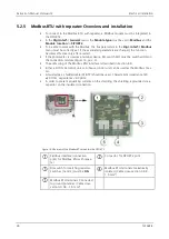
If the photometer is used as a terminal device, DIL switch S2/1 must be switched ON on
the connection module (Figure 13, pos. 3).
The addressing of the Profibus DP interface is described in Section 8.7.
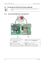
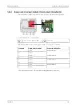
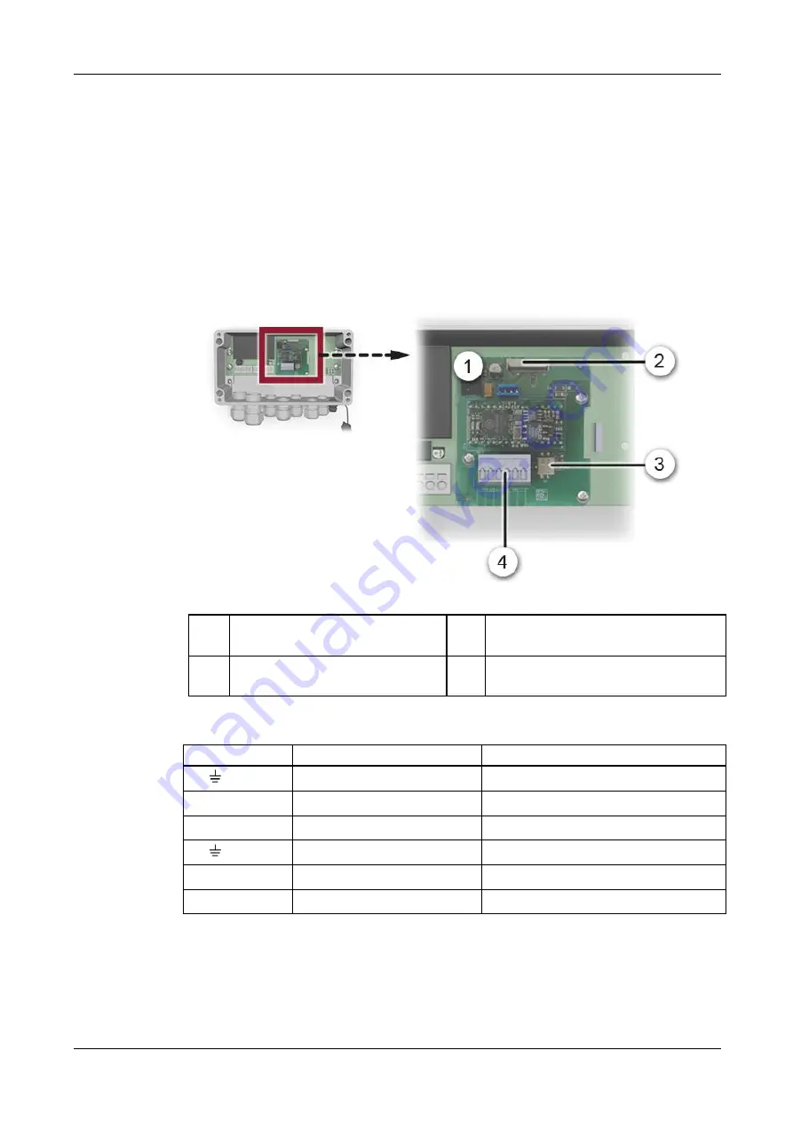
Figure 12: Overview of the Profibus DP module in the SIPORT 2
Fieldbus interface (connection
print) for Profibus DP
Connector for SIPORT 2 print
DIL switch for end resistors. Swit-
ches (1 and 2) must be
ON
Profibus DP terminals
(Cable cross-section: 0.08 .. 1.5 mm
2
)
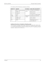
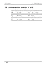
The Profibus DP/Modbus RTU terminals are assigned as follows:
TERMINALS
MODBUS / PROFIBUS
FUNCTIONAL DESCRIPTION
11
Ground IN
Connection for cable shielding
12 A
RS485-A IN
Data connection
13 B
RS485-B IN
Data connection
14
Ground OUT
Connection for cable shielding
15 A
RS485-A OUT
Data connection
16 B
RS485-B OUT
Data connection


