background image

21

 -

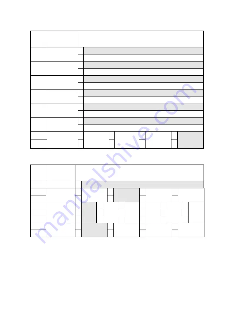
DIP switch 2

Posi-

tion

Function

Setting

1 Disabled

bit8

Initial status

automatic

transmission

0 Enabled
1 JIS code

bit7

Kanji

encoding

system

0 Shift JIS code
1 24-dot

bit6

Font size

0 16-dot
1 Disabled

bit5

Auto power

off

0 Enabled
1 Katakana character

bit4

Character set

0 Extended graphics
1 Enabled

bit3

Auto loading

0 Disabled

bit2

0

0

1

1

bit1

Transmission

mode

selection

0

BHT Ir

1

Serial

0

IrDA

1

Automatic
selection

DIP switch 3

Posi-

tion

Function

Setting

bit8

Not used

1 Fixed at "1"

bit7

0

0

1

1

bit6

Print density

0

- 5%

1

Standard

0

+ 5%

1

+ 10%

bit5

0

0

0

0

1

1

bit4

0

0

1

1

0

0

bit3

Paper

selection

*1

0

Thick
paper
(125 µm)

1

Thick
paper
(145 µm)

0

Normal
paper

1

High
proof
paper

0

2-ply
thermal
paper

1

Reserved

bit2

0

0

1

1

bit1

Paper mode

0

Cut sheet

1

Roll paper

0

Marked roll
paper

*2

1

Reserved

*1 If a setting not listed above is specified, thick paper (125 µm) is selected.

See Section 12, Options and Consumable Parts, for details of papers.

*2 For details, see DPU-3445-20 THERMAL PRINTER TECHNICAL REFERENCE.

Summary of Contents for DPU-3445-20

Page 1: ...USER S GUIDE Thermal Printer DPU 3445 20 Read this user s guide carefully before using the printer Keep this user s guide in a place where it can be accessed quickly Seiko Instruments Inc ...

Page 2: ...r is a trademark of DENSO INDUSTRIES INC is a trademark of Seiko Instruments Inc All other trademarks are the properties of their respective companies Applicable EC Directives and Standards Product Thermal Printer DPU 3445 10A DPU 3445 20A AC Adapter PW 3009 W2 Directives Title 89 336 EEC EC Electromagnetic Compatibility Directive Standards EMI EN50081 1 1997 EN55022 1994 Amd 1 1995 class B EN6100...

Page 3: ...ar installation It can be determined whether this equipment is causing interference by turning it off If the interference stops it was probably caused by the equipment If the equipment does cause interference try to correct the interference by one or more of the following measures Reorient or relocate the radio or television antenna Increase the separation between the equipment and the radio or te...

Page 4: ... following sections SAFETY PRECAUTIONS 2 OPERATING PRECAUTIONS 5 1 PREPARATION 7 2 NAMES OF PARTS 8 3 POWER CONNECTION 10 4 PAPER SETTING 12 5 TEST PRINTING 15 6 FUNCTION SETTING 16 7 CONNECTING TO THE HOST COMPUTER 22 8 RECHARGING THE BATTERY PACK 24 9 THERMAL HEAD MAINTENANCE 26 10 TROUBLESCHOOTING 27 11 SPECIFICATIONS 28 12 OPTIONS AND CONSUMABLE PARTS 29 For more detailed technical information...

Page 5: ...sonal injury or death CAUTION Failure to follow the guidelines marked with this symbol could result in minor personal injury or product and or peripheral damage Symbol Examples The symbol indicates caution including danger and warning The example on the left indicates warning or caution The symbol indicates prohibition The example on the left means prohibition of disassembling The symbol indicates...

Page 6: ...may lead to fires or personal injury DO NOT disassemble the battery pack because it may cause the battery pack to heat up and catch fire leading to other serious accidents DO NOT short the battery pack terminals as it may lead to fire electric shock or personal injury DO NOT subject the battery pack to direct sunlight or high temperature as it may lead to fire or personal injury Never disassemble ...

Page 7: ...thermal head immediately after printing because it becomes very hot Make sure that the thermal head is cool before clearing a paper jam or cleaning the thermal head Be sure to hold the connector part of the power cable or interface cable when disconnecting the cable Pulling on the cable portion may cause it to fray and break Power OFF the printer unplug the power cable from the power outlet and re...

Page 8: ... interface cable during printing X DO NOT cut any sheets of thick paper or label paper with the paper cutter installed in the paper outlet Failure to follow this instruction may cause a cutting error or make the cutting edge dull due to label paper adhesive sticking to the cutter X Switch the power off when not in use X Clean the printer using soft lint free cloth Do not use alcohol or other solve...

Page 9: ...ng or wet type copies X Do not use chemical glue X Always use the specified thermal paper See Section 12 Options and Consumable Parts for details Q Q Q Q Notations Used in this User s Guide The following two types of notations are used throughout this User s Guide to denote items of caution and items to remember NOTE X Operation Precautions This box contains items that when not followed may lead t...

Page 10: ...available as options Keep the package and packing materials for future transportation or long term storage The AC adapter and the battery charger is not bundled with an AC cable An AC cable should be ordered separately Printer Printer User s Guide this document Battery pack AC adapter AC cable Battery charger Paper holder ...

Page 11: ...ghts when the printer turns on See the Lamp Display on the next page for details 4 ERROR lamp The ERROR lamp lights when something is wrong with the printer See the Lamp Display on the next page for details 5 Infrared transmitter receiver The infrared transmitter receiver is used to communicate with the host device having the physical layer of IrDA which is in accordance with the standards of the ...

Page 12: ...ad cleaning 10 Platen roller The platen roller brings the paper in contact with the thermal head The platen roller is turned to feed the paper 11 Power connector Connects the AC adapter to this connector 12 Paper slot Paper inlet 13 Battery connection terminal Battery connection terminal 14 Battery release button Releases the battery pack from the printer Lamp Display Lamp display POWER lamp ERROR...

Page 13: ... the printer Installing the battery pack Remove the terminal cover from the battery pack Insert the battery pack in the direction of the arrow so that the printer connection terminal touches the connection terminal of the battery pack Removing the battery pack Turn the printer off Hold down the battery release button and slide the battery pack in the direction of the arrow HINT Read the instructio...

Page 14: ... AC cable to an electric outlet NOTE Before installing or removing the AC adapter turn the printer off If the printer is not used for a long time unplug the AC cable from the outlet HINT If the auto power off function is enabled the printer turns off automatically when it is not operated for 30 minutes to save the battery See Section 6 Function Setting for details on settings 1 2 3 ...

Page 15: ...ects the paper and loads it automatically 5 To discharge the paper from the printer hold down the FEED button CAUTION Take care not to get your fingers caught in the printer when loading paper NOTE Insert the paper into the slot straight If it is askew a paper feed error occurs DO NOT block the paper outlet or hold the paper that is being loaded Otherwise it may cause a paper jam HINT Marks for pa...

Page 16: ... Turn the printer on 3 If the printer has been stored without setting roll paper open and close the platen cover See Section 2 Names of Parts before setting the roll paper 4 Turn the printer over push the center of the paper cover and slide it in the direction of the arrow The paper cover is unlocked and can be opened 5 Set the roll paper in the paper holder as shown in the figure at the right Ins...

Page 17: ...therwise it may cause a paper jam DO NOT force the paper holder especially when the paper cover is open Q Q Q Q Removing the Paper Holder Cut sheets cannot be used with the paper holder installed To use cut sheets remove the paper holder 1 Remove the roll paper from the paper holder 2 Open the paper cover and push the right and left tabs of the paper holder at the same time to unlock them The pape...

Page 18: ...ded in the printer and the printer is off If the paper is not loaded load the paper as instructed in Section 4 Paper Setting and turn the printer off 2 Press the POWER and FEED buttons at the same time When the POWER lamp lights release the POWER button then the FEED button 3 Several dozens of lines of text are printed DPU 3445 Ver Copyright C SII 4 After test printing the printer goes into standb...

Page 19: ...er is off If the paper is not loaded load the paper as described in Section 4 Paper Setting and then turn the printer off HINT If an error occurs in the function setting mode the POWER and ERROR lamps blink 3 to 4 times and the power is turned off 2 Press the POWER and FEED buttons at the same time When the POWER lamp lights and five seconds later the POWER and ERROR buttons start blinking release...

Page 20: ...ettings To set the settings to defaults perform operation 1 To change settings perform operation 2 1 Initializing software DIP switch settings 1 When the message shown at the right is printed in the function setting mode press the FEED button Load Default Setting Yes Feed SW No Power SW 2 When the message shown at the right is printed the printer turns off The settings are set to defaults Initiali...

Page 21: ... POWER lamp blinks once Verify that the POWER lamp blinks Operation 1 DIP switch selection If you press the FEED button when the message shown at the right is printed you can perform operation 2 If you press the POWER button instead of the FEED button the details of the printed DIP switch DIP switch 1 are not changed and the next DIP switch is selected operation 1 DIP Switch setting mode DIP SW 1 ...

Page 22: ...age shown at the right is printed and the setting is not changed DIP SW 1 Not Changed After this operation you can select the next DIP switch operation 1 After setting DIP switch 3 you can exit function setting mode operation 3 HINT in the message indicates the setting of the DIP switch The leftmost bit is the most significant bit bit 8 and the rightmost bit is the least significant bit bit 1 Oper...

Page 23: ...t1 Baud rate bps 0 1200 1 2400 0 4800 1 9600 0 19200 1 38400 0 57600 1 115200 1 This setting is enabled only when Serial is selected as the transmission mode with DIP switch 2 When BHT Ir is selected as the transmission mode with DIP switch 2 the baud rate is set to 2400 bps automatically 2 This setting is enabled only when BHT Ir is selected as the transmission mode with DIP switch 2 When Serial ...

Page 24: ...DA 1 Automatic selection DIP switch 3 Posi tion Function Setting bit8 Not used 1 Fixed at 1 bit7 0 0 1 1 bit6 Print density 0 5 1 Standard 0 5 1 10 bit5 0 0 0 0 1 1 bit4 0 0 1 1 0 0 bit3 Paper selection 1 0 Thick paper 125µm 1 Thick paper 145µm 0 Normal paper 1 High proof paper 0 2 ply thermal paper 1 Reserved bit2 0 0 1 1 bit1 Paper mode 0 Cut sheet 1 Roll paper 0 Marked roll paper 2 1 Reserved 1...

Page 25: ...ssion An interface cable is required to perform serial transmission An interface cable that fits into the host computer must be selected See Section 11 Specifications for details of interface specifications Q Q Q Q Serial Transmission with an Interface Cable CAUTION When plugging or unplugging the interface cable hold the connector not the cable When removing or installing the interface cable turn...

Page 26: ...mitter receiver of the printer as shown in the figure 4 Check the transmission status from the host computer 5 Send data from the host computer to the printer Verify that the printer prints it correctly HINT The positions shown in the figure are for reference The best positions depend on the model and environmental conditions NOTE The host computer must conform to IrDA Ver 1 0 or BHT Ir protocol W...

Page 27: ... button for five seconds The POWER lamp lights and starts blinking When the lamp starts blinking recharging begins 6 The POWER lamp will continue to blink while recharging When recharging is complete the POWER lamp lights continuously At this time when the paper is not set or the platen cover is opened the ERROR lamp lights The recharging time depends on the ambient temperature and the voltage lev...

Page 28: ...E lamp goes off the battery pack is sufficiently recharged for use practical recharging When the battery pack is recharged for an additional hour then it is fully recharged 4 When recharging is complete remove the battery pack To remove the battery pack slide it in the opposite direction of that for installation NOTE When the charger is connected to the outlet do not bring any metal object into co...

Page 29: ...wer off 2 Open the platen cover When the platen cover is fully opened the thermal head moves away from the platen roller 3 Clean the thermal head with a cotton swab moistened with a small amount of ethyl alcohol 4 Wait until any ethyl alcohol remaining on the thermal head and the platen roller evaporates completely then close the platen cover NOTE Clean the thermal head after it cools Wipe the the...

Page 30: ... the User s Guide being used Is the IrDA transmission status good Are the transmission conditions for the printer and the host computer correct Is the recommended paper being used Is the paper orientation top bottom correct Q Q Q Q The ERROR lamp is lit or the POWER lamp blinks See the Lamp Display on page 9 Is the printer function setting correct Q Q Q Q The battery pack Is not installed Is the b...

Page 31: ...apter PW 3009 W2 Specifications Option Item Specification Input voltage 100 240 VAC 50 60 Hz Output capacity 9 3 VDC 3A Operating temperature 0 C to 40 C Dimensions W D H 128 49 25 4mm 1 Weight Approx 200g 1 1 Excluding power cable Q Q Q Q Battery charger BC 3008 W1 Specifications Option Item Specification Input voltage 100 240 VAC 50 60 Hz Output capacity 10 W recharging 100 V 17 W recharging 240...

Page 32: ...be used both for the AC adapter and exclusive battery charger Does not apply to those exported to the U S Q Q Q Q Paper Name Model Specification Thick paper 125 µm TS 341 125 112 mm width x 158 mm length cut sheets Thick paper 145 µm TS 341 145 112 mm width x 158 mm length cut sheets Normal paper TP 341L 1 112 mm width 48mm diameter roll High proof paper TP 343L 3 112 mm width 48mm diameter roll 2...

Page 33: ...b D 63263 Neu lsenburg Germany Telephone 49 6102 297 0 Facsimile 49 6102 297 116 Seiko Instruments H K Ltd 4 5 F Wyler Centre 2 200 Tai Lin Pai Road Kwai Chung N T Kowloon Hong Kong Telephone 852 2421 8611 Facsimile 852 2480 5479 Seiko Instruments Taiwan Inc 4F No 40 Sec 2 Min Chuan E Rd Taipei 104 Taiwan R O C Telephone 886 2 563 5001 Facsimile 886 2 521 9519 Seiko Instruments Singapore Pte Ltd 2...

Reviews: