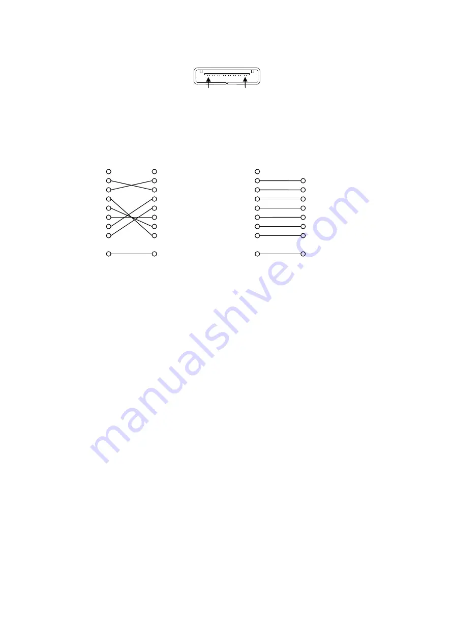
3-2
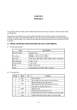
(3) Connector
3260-8S3: HIROSE ELECTRIC CO., LTD. or equivalent
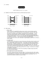
(4) Examples of connection with the host device (a standard personal computer)
(5) Data
reception
Busy control
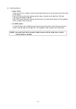
In Busy Control, RTS outputs MARK until the printer is ready to receive data after power ON.
After the printer is ready, RTS outputs SPACE and the received data is input to the input buffer.
When there are 33 bytes or less remaining in the input buffer, RTS outputs MARK. The host
device does not transmit data during RTS outputs MARK. When the input buffer is ready to
receive data (there are 65 bytes or more in the input buffer) after stopping data reception, RTS
once again outputs SPACE. If an error occurs in the printer, RTS outputs MARK and inhibits data
entry until the error is cleared. If an error is cleared, RTS outputs SPACE again.
For RTS output when an error occurs, the setting is changed by Busy Output When Error Occurs at
function setting.
Xon/Xoff control
In Xon/Xoff control, TXD outputs Xon code (11H) from power ON until the printer is ready to receive
data. Received data is input to the input buffer. When there are 65 bytes or less remaining in
the input buffer, TXD outputs Xoff code (13H). The host device does not transmit data while Xoff
code is received. When the input buffer is ready to receive data (there are 129 bytes or more in
the input buffer) after stopping data reception, TXD once again outputs Xon code. When this
control method is selected, the RTS signal always outputs SPACE. If an error occurs in the printer,
TXD outputs Xoff code and inhibits data entry until the error is cleared. When the error is cleared,
TXD outputs Xon code again.
For Xoff code transmission when an error occurs, the setting is changed by Busy Output When
Error Occurs at function setting.
Data reception error in serial communication
When Parity is selected as Yes by the function setting, a '!' is printed next to data in which a parity
error occurred and a '?' is printed next to data in which any other error (framing error, etc.) occurred.
If a serial data reception error occurs, no error indication other than the printing of '!' and '?' is
performed (for example, the ERROR lamp does not light).
CTS 7
DTR 6
GND 5
DSR 4
RXD 3
TXD 2
Host device
Printer
N.C. 1
RTS 8
20 DTR
7 S.G
6 DSR
5 CTS
4 RTS
3 RXD
2 TXD
1 F.G
CTS 7
DTR 6
GND 5
DSR 4
RXD 3
TXD 2
Host device
Printer
N.C. 1
RTS 8
7 RTS
6 DSR
5 S.G
4 DTR
3 TXD
2 RXD
8 CTS
SHELL
SHELL
(Shield)
SHELL
SHELL
(Shield)
8-pin – 25-pin
8-pin – 9-pin
8
1
Summary of Contents for DPU-S245
Page 1: ...DPU S245 SERIES THERMAL PRINTER TECHNICAL REFERENCE U00117152801 ...
Page 12: ...2 2 Dimensions 83 130 45 1 3 63 5 75 2 9 7 38 Unit mm Figure 2 1 Dimensions Paper Outlet ...
Page 87: ...6 42 Figure 6 10 Print Sample 5 ...
Page 97: ...6 52 Figure 6 12 Print Sample 6 ...
Page 122: ...6 77 Figure 6 24 Print Sample 12 ...
Page 125: ...6 80 Figure 6 28 Print Sample 14 ...


