background image

2-27

2

Ba

sic O
pe

ra

tio

n

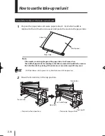
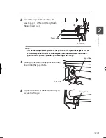
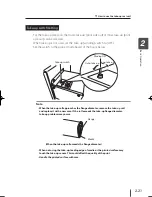
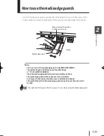
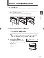
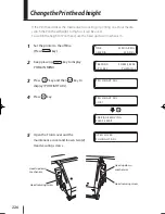
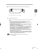
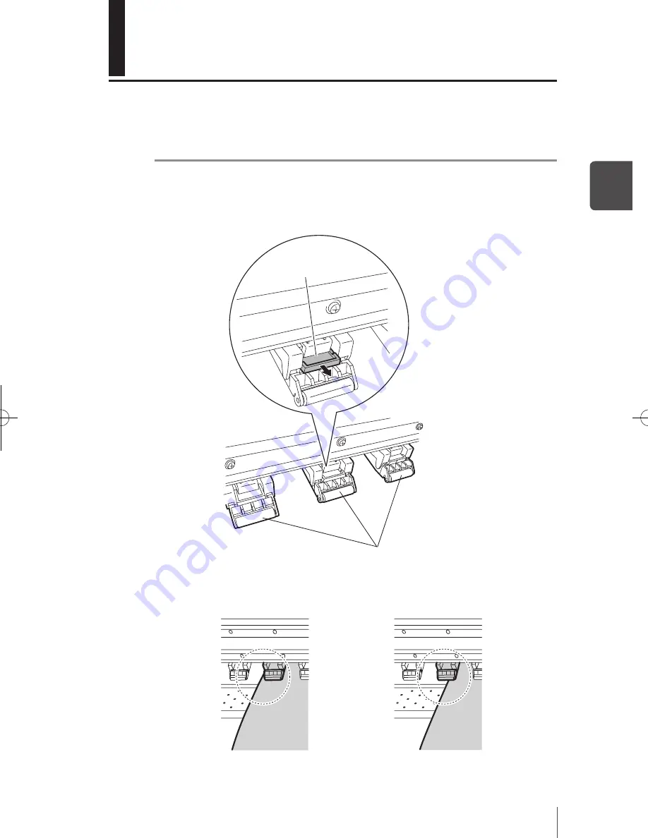
Example of when it is not necessary to 

pull the lifter toward you (The pressure of 

pressure roller is needed.)

Example of when pulling the lifter 

toward you (Releasing the pressure 

force of pressure roller is needed.)

How to use the lifter

Unless the media is under the entire pressure roller, wrinkles and skews may occur.
In such case, pull toward you the lifter at the upper side of pressure roller to re-
lease the pressure force of pressure roller.


Note

-

 Wrinkles may be eliminated in all medias.

Lifter

Pressure roller

IP-5610取説_E.indb   27

09.4.3   3:14:10 PM

Summary of Contents for IP-5610

Page 1: ...User s Guide Read this User s Guide before operating the printer Save this manual for future reference Solvent Ink Color Inkjet Printer IP 5610 Seiko I Infotech Inc U00114186301 ...

Page 2: ...029 USA Phone 1 760 781 5200 Fax 1 760 745 1195 Seiko I Infotech Inc 8 Nakase 1 chome Mihama ku Chiba shi Chiba 261 8507 Japan Phone 81 43 211 1363 Fax 81 43 211 8709 This guide acknowledges the following trademarks is a trademark of Seiko Instruments Inc All other trademarks are the properties of their respective companies This equipment has been tested and found to comply with the limits for a C...

Page 3: ...he EMC directive 2004 108 EC and low voltage directive 2006 95 EC Inquiry of CE mark Seiko Instruments Europe S A European Head Office Avenue de Messidor 198 1180 Brussels Belgium Phone 32 0 2 346 62 74 Fax 32 0 2 347 52 68 Seiko I Infotech A Division of Seiko Instruments USA Inc 2060 Wineridge Place Suite A Escondido CA 92029 USA Phone 1 760 781 5200 Fax 1 760 745 1195 Seiko I Infotech Inc 8 Naka...

Page 4: ......

Page 5: ...Inkjet Printer User s Guide de scribes such information for use as features and functions of the printer and the printing procedure In addition troubleshooting is also described Read sections suitable for your purpose The following items should be read before reading Section 1 Components delivered with this product Safety precautions Handling precautions Manual legend notational rules Read these i...

Page 6: ......

Page 7: ...0114 186300 Read this User s Guide well before use of this printer and handle it properly After reading keep it for later use User s Guide Solven t Ink Color Inkjet Printe r IP 5610 Seik o I Infot ech Inc Waste ink bottle 1 bottle Ink is consumed during the initial filling when the printer is installed Therefore all of ink may not be used for printing Basic configuration item Supplied Accessories ...

Page 8: ...eces Storage liquid cartridge set IP5 107 1 set Storage liquid cartridge 6 pieces Cap cleaning liquid set IP5 136 1 set Wipe cleaning liquid set IP5 231 1 set Wipe cleaning liquid 200 ml 3 bottles Cleaning swab IP6 147 300 pieces Options Consumables Waste ink bottle IP5 139 1 piece Wiper blade IP5 122 2 pieces Ink cartridge Y M C K Lc Lm g As to types refer to P 1 12 Daily maintenance kit IP5 230 ...

Page 9: ... in this manual to ensure the proper use of the printer and to prevent the printer from being damaged Follow the instructions marked with these symbols Minor personal injury or product and or peripheral damage Failure to follow the guidelines marked with this symbol could result in minor personal injury or product and or peripheral damage Serious personal injury or death Failure to follow the guid...

Page 10: ...remely hot parts Doing so may might result in an electric shock or burn DO NOT allow metal or liquids to touch the internal parts of the printer Doing so may cause fire electric shock or personal injury DO NOT disconnect or connect the power cable with wet hands Doing so may lead to electric shock Turn the printer off and unplug the power cable immediately after it thun dered Power OFF the printer...

Page 11: ...arts may be broken or paints may come off Since the media rolls are heavy handle them with care If dropped personal injury may result Always hold the power cable or the USB cable by the plug or the connector when connecting or disconnecting the power cable or the USB cable Never pull on the cable because this may damage it and create risk of fire elec tric shock or personal injury DO NOT get ink o...

Page 12: ...e surface of the cover with benzene or paint thinner The coating may come off or deteriorate Wipe the cover clean with a soft cloth If the cover is very dirty use a cloth moist ened with a neutral detergent 5 Handle a Print head with care Do not touch it unnecessarily or scratch it Do not touch the bottom nozzle surface Regular inspection and maintenance As the intrinsic characteristics of dye sub...

Page 13: ...oor with spilled ink 7 Store ink in a dark and cool place NEVER store ink in a high temperature or direct sunlight Ink change characteristic if exposed to direct sunlight 8 Do not use media other than the media specified by Seiko I Infotech Doing so may cause printed image quality problems or damage the printer Printer warranty 1 To understand the performances and functions of this printer and use...

Page 14: ...d with a CAUTION describe points of caution for avoiding injury to yourself or damage to the printer Note They explain the important items and cautions that should be kept when operated To avoid troubles of the printer or prevent damages or wrong operation ensure to read HINT Hint mark The hint symbol describes operations that make using or handling the printer easier Reference mark This mark is f...

Page 15: ...the function menu with key shows the key on the operation panel shows the LCD on the operation panel Key LCD notations Shows the key to be used for selection Example h key hINK MEDIA REGi fMEDIA M ADVg hREWIND FORM FEEDi fPH REC PH MAINg Example2 TransitionofLCDstateandthekeyoperationinasentence Shows that the LCD menu switches with key operation INITIALIZING PLEASE WAIT hINK MEDIA REGi fMEDIA M A...

Page 16: ...ead height Print mode Starting out Starting out Connect to a computer Turn on the power Replace the ink cartridge Load the roll media Replace the media Register the media Turn off the power P 2 2 P 2 3 P 2 38 P 2 3 P 2 12 P 2 7 P 2 14 ...

Page 17: ...spection Maintenance Clean the Capping unit Check stains on the Wiper Blade Implementation of Print head cleaning NORMAL ALL Check the wipe cleaning liquid Check the Waste ink bottle Implementation of nozzle print Implementation of nozzle print P 4 6 P 4 3 P 4 4 P 4 3 P 4 19 P 4 8 ...

Page 18: ...e thick media Change the heater temperature during printing Switch off the printer for a long period of time Clean the printer Print on the margin of media When you want to When you want to Print on the cut media sheet P 2 15 P 2 31 P 4 32 P 2 36 P 2 33 P 4 10 P 4 14 ...

Page 19: ...f the media Adjustment of the Print head bi direction position Adjust the ink target position in the bi directional print When replacing with new media With new media the printer needs to be adjusted With new media the printer needs to be adjusted P 4 28 P 4 34 ...

Page 20: ...he media is slantingly advanced The heater does not warm up Smears or stripes appear on the print The panel operation becomes inoperative The panel operation becomes inoperative Wiper blade Waste ink bottle Replacement Trouble Replacement Trouble P 5 13 to P 5 15 to P 4 25 P 4 27 P 4 23 P 4 21 P 2 38 P 5 6 P 5 13 P 2 7 P 2 24 P 2 25 P 2 31 ...

Page 21: ...ad 1 6 Capping unit 1 6 Blower unit 1 6 Printer heater unit 1 7 Operation Panel 1 8 Options 1 9 Exhaust attachment 1 9 2 inch flange 1 9 3 inch flange 1 9 Consumables 1 10 Media 1 10 Ink 1 12 Waste ink bottle 1 14 Daily maintenance kit 1 15 Cap cleaning liquid 1 15 Wiper cleaning liquid set 1 16 Cap cleaning stick 1 16 Cap cleaning roller set 1 16 Cleaning swab 1 16 Wiper blade 1 17 Media cutter b...

Page 22: ... switch setting 2 21 Using a 2 inch core 2 22 How to use the blower unit 2 23 Set the blower unit to the printer 2 23 Handling the media 2 24 How to use the media edge guards 2 25 How to switch the pressure 2 26 How to use the lifter 2 27 Cut the media 2 28 Feeding the media Feed 2 29 Rewind the media Back Feed 2 30 How to use the origin setting function 2 31 Changing temperature using the heater ...

Page 23: ...dic maintenance 4 2 Periodic inspection Maintenance guide 4 2 Cleaning 4 14 Print head cleaning 4 19 Operating procedure of Print head cleaning 4 19 Wiper blade replacement 4 21 Wiper cleaning liquid replacement 4 23 Wiper sponge replacement 4 25 Media cutter blade replacement 4 27 Media advance value setting 4 28 Media advance value setting procedure 4 28 Change during online printing 4 32 Head p...

Page 24: ...d 5 13 How to get good image quality 5 15 Abnormal sound 5 25 Use of generic consumables Printer warranty and safety issues 6 2 Printer warranty 6 2 Safety issues 6 2 Use of generic consumables 6 3 To use a re filled ink cartridge 6 3 To use an generic ink cartridge 6 4 Cleaning liquid 6 5 Appendix Basic specifications A 2 Printer Specifications A 2 Options Consumables A 3 Options A 3 Consumables ...

Page 25: ...using the printer basic knowledge After reading this section proceed to section 2 Overview Operating conditions 1 2 Appearance Name and function of each part 1 4 Options 1 9 Consumables 1 10 LCD display and state of printer 1 18 Content in this section 1 ...

Page 26: ...nstallation space The adequate space is required around the printer for normal operations including supplies replacement print processing blower unit shifting and ventilation as well as parts replacement for repairing Installation and maintenance space 400mm 16 inches 400mm 16 inches 2000mm 80 inches 1000mm 40 inches Front side ...

Page 27: ...quality may be degraded and or print may be stopped It takes time for the printer to reach the operating environment temperature and humidity To get good printed image quality it is recommended to keep the room temperature 20 to 25 C 68 to 77 F and use the printer after 1 hour Places where the printer must not be installed Do not install the printer in the following places Places exposed to direct...

Page 28: ...functions are assigned Media cutter blade It cuts the media Waste ink bottle Maintenance tool holder It is convenient to store the Maintenance tool Media clip After cutting the media it clips the media so as not to drop Front paper guide Tension bar Take up sensor Media clip After cutting the media it clips the media so as not to drop Grid roller The grid roller advances or rewinds the media Press...

Page 29: ...t turns on or off the power of the printer USB connector Connect the USB2 0 cable to the USB connector Ink cartridge slot Set the ink cartridges in these slots Flange holder Place the media with flange on the flange holder Flange Install it to the both sides of the roll media Pressure roller up down lever This lever fixes or releases the media It is inter linked with the pressure roller up down le...

Page 30: ...d by 0 5mm Print heads Projects ink to the media Carriage Capping unit Wiper blade It removes foreign matters on the surface of nozzle of the Print head Capping unit It prevents the nozzle of the Print head from drying Blower unit Blower unit This unit dries ink by sending air to the media ...

Page 31: ...eater Penetrates ink into media to fuse the ink Front heater Dries ink to stabilize print quality Media feed direction Media Print head Carriage Paper guide rear These three heaters are controlled independently P 2 33 Changing temperature using the heater control menu WARNING Do not touch these heaters to avoid burn as they become hot q Appearance Name and function of each part ...

Page 32: ...ed to cancel the parameter entered Used as the input auxiliary switches the layer display of the menu key of the parameter Used to fix the menu and parameters Used to enter heater control menu Use for selecting the menu group and switching the menu selection increment decrement of numeral value Data LED Green It indicates the data reception state Blink The printer is receiving the data from a comp...

Page 33: ... 1 Options Exhaust attachment An optional unit to attach an exhaust duct to the printer 2 inch flange This flange is used to load the roll media of 2 inch core 3 inch flange This flange is used to load the roll media of 3 inch core ...

Page 34: ...media Dispose of media in a manner consistent with local regulations Precautions for preparing media Avoid a change of temperature and humidity after opening package Load media after leaving media in the operation environment for 3 hours or more Be cautious changing humidity by turning air conditioners ON or OFF Curl of paper in low humidity and wrinkle of media in high humidity may occur easily U...

Page 35: ... may damage the prints Do not rub scratch or fold the printed surface of media Color may be lost or the surface coated layer of the media may come off Do not leave the paper in wet environment Other Precautions of media Media causes color fading and a change in quality in getting old Dust and debris produced when cutting the media may cause the lost color When the thin media is used the platen may...

Page 36: ...se only the recommended ink cartridges listed below Type Content Quantity IP5 201 Y Yellow 500 ml IP5 202 M Magenta 500 ml IP5 203 C Cyan 500 ml IP5 204 K Black 500 ml IP5 205 Lc Light cyan 500 ml IP5 206 Lm Light magenta 500 ml Note Failure to use the recommended ink cartridge may lead to a deterioration of the print quality or a printer malfunction This may invalidate your warranty Install all o...

Page 37: ... with clean water and consult a doctor immediately If it is swallowed do not try to induce vomiting Seek medical attention immediately CAUTION Do not attempt to disassemble ink cartridges Precautions for ink storage and processing CAUTION Securely put a used ink cartridge into a plastic bag and dispose of it as a hazardous waste Observe any local regulations for disposal of ink cartridges ...

Page 38: ...ets into the eyes rinse with clean water and consult a doctor immediately If it is swallowed do not try to induce vomiting Seek medical attention immediately CAUTION Install the Waste ink bottle securely A Waste ink bottle must always be installed If it is removed for replacement a new one must be installed Precautions for handling the Waste ink bottle CAUTION After use securely fasten the attache...

Page 39: ...octor Do not keep the cap cleaning liquid and the wipe cleaning liquid in a high temperature place or in direct sunshine Never place the cap cleaning liquid close to open flames Doing so will create a fire hazard Cap cleaning liquid Use the following Cap cleaning liquid specified by Seiko I Infotech Type Content Quantity IP5 136 Cap cleaning liquid 300 ml 1 piece WARNING Do not swallow cap cleanin...

Page 40: ...n immediately Do not keep the Wiper cleaning liquid bottle in a high temperature place or in direct sunshine Never place the wiper cleaning liquid close to open flames Doing so will create a fire hazard Cap cleaning stick Use the following Cap cleaning stick specified by Seiko I Infotech Type Content Quantity IP5 120 Cap cleaning stick 1 piece Cap cleaning roller 1 piece Cap cleaning roller set Us...

Page 41: ... Media cutter blade 1 piece Wiper sponge Use the following Wiper sponge specified by Seiko I Infotech Type Content Quantity IP5 123 Wiper sponge 1 piece Storage liquid cartridge set Use the following Storage liquid cartridge specified by Seiko I Infotech Type Content Quantity IP5 107 Storage liquid cartridge 6 pieces Cleaning liquid cartridge set Use the following Cleaning liquid cartridge specifi...

Page 42: ...d LCDdisplayandstateofprinter This section illustrates how to read the LCD display and the state of printer How to read LCD 1 Initialization display Shows the initialization of the printer at the start up is being processed When the printer starts up normally it automatically enters the idle online mode PRINTING ROLL 1625 PAPER Booting up INITIALIZING PLEASE WAIT PRINTER READY ROLL 1625 PAPER Medi...

Page 43: ...hts Whenresumingprintingafterpaused 6 ONLINE state preheating This message indicates that the heater is in heating process to reach the preset temperature 7 ONLINE state During head warming up This message indicates that the heads are warming up Head warming up is conducted when the room temperature temperature inside the printer is low Recommended room temperature is 20 to 25 C Head warming up is...

Page 44: ...interval or REMAINING MEDIA xxxm When the daily maintenance is not performed or the life and replacement time of consumable parts approaches the following messages appear The display next returns to the ONLINE state YY INK NEAR EXPIRATION DATE Every 3 seconds interval or Every 3 seconds interval or PERFORM DAILY MAINTENANCE NOW XXXXXX CALL SERVICE When the daily maintenance is not implemented as u...

Page 45: ...LINE state menu mode display This illustrates that the menu operation available in the offline state P 3 2 Basic menu operation in offline mode hifg denotes the access key to each menu By pressing the key in the menu mode display Cleaning Menu is activated SHUTTING DOWN PLEASE WAIT hINK MEDIA REGi fMEDIA M ADVg hPRINTER SETUPi fADJUST HEATERg hREWIND FORM FEEDi fPH REC PH MAINg ...

Page 46: ......

Page 47: ...unit 2 23 How to use the media edge guards 2 25 How to switch the pressure 2 26 How to use the lifter 2 27 Cut the media 2 28 Feeding the media Feed 2 29 Rewind the media Back Feed 2 30 How to use the origin setting function 2 31 Changing temperature using the heater control menu 2 33 Change the Print head height 2 36 Ink cartridge replacement 2 38 Waste ink bottle replacement 2 40 Content of this...

Page 48: ...nnected the printer may not function properly To protect the USB connector clamp the USB2 0 cable to the printer body Connecting procedure Connect the cable in the procedure below 1 Turn off the power of the printer and computer to be connected Note When the printer and a computer are connected turn on the power of the printer first and turn off the power of printer last when powering them down 2 ...

Page 49: ...Use the power switch on the operation panel of printer whenever subsequently turning the power on or off Note When the printer and a computer are connected turn on the power of the printer first and turn off the power of printer last when powering them down Main Power Switch ...

Page 50: ... on the operation panel When turning on the power the printer performs the power on self diagnostic test and displays the following message on the operation panel Note When the printer is performing INITIALIZING or CLEANING if the power is removed unnecessarily ink may drip or the Print head may be damaged Switch off O Power switch Power inlet Example of the set roll media of 1625 mm PRINTER READY...

Page 51: ...ge of the 100 200 V switch conform to the local specifications If the LED on the operation panel does not light when the main power switch at the rear of printer and the power on off switch on the operation panel are turn on the power supply is defective When a problem is detected in the power on self diagnostic test the error message is displayed on the LCD Refer to Section 5 Troubleshooting for ...

Page 52: ...cap operation is skipped and the power will be turned off However executing the fill cap operation is normally recommended Note When the printer power needs to be completely turned off for transportation connection to a computer replacement of internal parts use the main power switch at the rear of printer After turning the power off using the power switch in the rear of the printer wait at least ...

Page 53: ...cer to the flange at the right hand side 3 While holding the flange spacer in place insert the flange in the media Push the flange in as far as it goes Note When inserting the flange in the roll media be careful not to cause the media to shift on the roll or damage the end surface of roll media Roll media Mediareplacement This section describes Roll media installation removal procedure There two s...

Page 54: ...acer to the flange 2 Insert the flange in the roll media 3 Push the flange as far as it goes and fix the flange by turning the knob 4 Pull out the flange spacer Note When the end of the media is glued to the core the glue may stick to the paper guide and platen If this happens remove the glue and clean the platen 6 Place right and left flanges on the roll so they set on the flange holders Roll med...

Page 55: ... When the leading edge of media comes out of the Front cover a confirmation beep sounds Note Depending on the environment it may be hard to advance the media due to it sticking to the paper guide In this case advance the media while raising the media from the paper guide by holding both edges of media by hand If the leading edge of media is curled up or curled down the media may be caught in the p...

Page 56: ...t time Note If you shift the media only skewing will occur So adjust the load position by moving the media and flange holder together 10 Secure the position of flange holders by tightening the screw of flange holder at the left hand side 11 Hold the center of media by hand and turn back the flange to eliminate the slack Note Do not forcibly align the edge surface of media to the general rule line ...

Page 57: ...ver the both ends of media Then close the Front cover Ensure that the media edge guards do not fall under the media and that thick media does not bind After visually confirming that the media edge guards are properly set press the key 14 Select either the roll media or the cut media sheet Either roll or sheet can be selected with key or key Here select roll and press the key To return to the media...

Page 58: ... platen has no curl or wrinkles To register a new media 15 Select the type of media Select the type of media registered with the and keys and press the key P 3 20 MEDIA REG MENU REMAINING MEDIA XXXm PREPARING MEDIA PLEASE WAIT NEW MEDIA ENTRY is displayed at the end of the registered media Press the key to enter MEDIA REG MENU The media registration procedure is the same as the registration from t...

Page 59: ... Raise the pressure roller up down lever 2 Rewind the flange to roll back the media 3 Unload the roll media from the flange holder 4 Loosen the knob and remove the flange from the media Pressure roller up down lever Flange Flange Knob q Media replacement ...

Page 60: ...glued to core the printer may not automatically detect If printing is continued the printer may be stained or damaged Visually check the remainder of media 1 The message appears on the LCD screen 2 After this according to Media installation removal procedure replace the media When replacing the roll media due to jamming Refer to Section 5 Troubleshooting How to clear media jams NO MEDIA LOADED LOA...

Page 61: ... the leading edge of media comes out of the Front cover 4 Move the media so that both ends of media are evenly applied to the pressure roller 5 Lower the pressure roller up down lever Follow the instructions on the LCD screen Note Select SHEET for SELECT MEDIA When selecting SHEET the remaining media cannot be entered Cut media removal procedure 1 Raise the pressure roller up down lever and remove...

Page 62: ...st the paper tube it will cause skew The width of paper tube for winding in the take up reel unit should be the same as that of roll media for printing If the wider one is used take up shift may occur Shift the blower unit to prevent any interference with the operation 2 Move the Tension bar in the top position About 1m Tension bar Tension bar Paper tube Waste paper Tension bar fixed position Tens...

Page 63: ...on of the right side flange it is used as the fixed position However when aligning with the roller media installation position to the printer adjust the position of right side flange 4 Sliding the left side flange movable side insert it in the paper tube 5 Tighten the knob at the left side firmly to secure the flange Paper tube Left side Right side Fixing knob Paper tube ...

Page 64: ...down lever and install the roll media for printing to the printer For media installation procedure refer to P 2 7 Media replacement 8 By operating the feed menu on the operation panel advance the media until it reaches the leader paper 9 Joint the roll media and leader paper Affix at three locations right left and center with adhesive tape Bottom position of Tension bar Pressure roller up down lev...

Page 65: ...nd the take up sensor If not re install the media Take up sensor Take up sensor The media locates over the take up sensor The media penetrates under the take up sensor Media Media Media Take up sensor Flange Incase of revolution When used with print side in rotate the flange in the reverse direction of arrow to eliminate the slack q How to use the take up reel unit ...

Page 66: ...oose configuration can be selected In normal use the loose method is preferred ø Tension take up configuration ø Loose take up configuration SELECT MEDIA XX YYYYYY Operation panel LCD display TUR MODE XX LOOSE Tension take up configuration Loose take up configuration setting procedure In TUR MODE of MEDIA REG MENU set the tension configuration XX Media number YYYYYY Media name TUR MODE XX TENSION ...

Page 67: ...ge of media or the printed surface may touch the take up sensor This could affect the quality of the print Handle the printed surface with care Inner take up Winding OFF Outer take up Take up switch setting For the take up direction the Outer take up print side out or Inner take up print side out can be selected When take up is not used set the take up winding switch to OFF Set the switch to the p...

Page 68: ...nstall the removed attachment into the left and right plates to keep them for later use See the figure at the right hand side Insert the 3 inch adapter in the slits holes of the left and right plates and turn clockwise in the arrow direction When installing the 3 inch adapter to the flange again push the hook projection of 3 inch adapter in the slits holes of flange Turn the adapter clockwise in t...

Page 69: ...f the printer stand 2 Push the blower unit until the bar touches the printer stand 2 Wind the cable around the hook Howtousetheblowerunit The blower unit is installed to the paper exit side of the printer and is used to ef fectively dry the printed media ink processed by the printer Printer stand Blower unit stand Blower unit bar Printer stand Cable Hook ...

Page 70: ...t dry completely on some media In this case set the paper scanning wait time P 3 25 from the operation panel of the printer Handling the media Shift the blower unit to prevent any interference before installing the media to the printer P 2 7 installing the media on the take up reel unit P 2 16 and cutting the media P 2 28 Printer Blower unit ...

Page 71: ...edia edge guard in the MEDIA REG MENU The widths of right and left margins of media change P 3 28 8 EDGE GUARD Clean the media edge guards when ink accumulates on them The media edge guards will not prevent curl on all media As it causes the lost print eliminate waves and folds beforehand The media thicker than the media edge guard cannot be used Do not insert it forcibly The right and left margin...

Page 72: ...e is switched by the posi tion of the pressure roller up down lever See figure below No pressure top When loading the media raise the lever This the normal UP position Rear Front Normal Pressure bottom When loading the media lower the lever It is the normal DOWN position Weak In the center The pressure force becomes weak No Pressure top When loading the media raise the lever It is the normal UP po...

Page 73: ...r toward you Releasing the pressure force of pressure roller is needed Howtousethelifter Unless the media is under the entire pressure roller wrinkles and skews may occur In such case pull toward you the lifter at the upper side of pressure roller to re lease the pressure force of pressure roller Note Wrinkles may be eliminated in all medias Lifter Pressure roller ...

Page 74: ...tter blade by hand and pull it out 2 Rotate the Media cutter blade so that the left side comes to the right side and then insert it Note If the Media cutter gets stuck while cutting return the cutter blade to the side and check it is not broken Remove the cause of the binding and cut the media slowly moving the Media cutter blade Some medias are hard to cut Do not forcibly cut difficult media Doin...

Page 75: ...ey While pressing key the roll media is fed When cut sheet media is used the paper is ejected 4 When releasing your hand off key feeding stops the printer returns to the offline state menu mode When the online state idle mode is displayed if key is pressed the media can be fed without entering in the FORM FEED MENU hINK MEDIA REGi fMEDIA M ADVg hREWIND FORM FEEDi fPH REC PH MAINg hREWIND FORM FEED...

Page 76: ...ode The paper ejection sensor that detects the presence absence of media is installed to the front paper guide If the media covers the paper ejection sensor the media can be fed back When you keep pressing key the media can be fed back at a distance of 14 cm at maximum from the paper ejection sensor When the online idle mode is displayed if key is pressed the media can be fed without entering in t...

Page 77: ...Procedure of how to use the origin setting function 1 Return the media by operating Back Feed P 2 30 Rewind the media Back Feed Note Return the media only after the printed image completely dries The first printed image will be damaged if this function is used before it is sufficiently dry 2 Press and hold the key for 1 5 seconds in the online state idle mode the carriage moves and the origin sett...

Page 78: ...nline state idle mode display To release the set origin keep press and hold the key for 1 5 seconds in the idle mode or raise the pressure roller up down lever to release the set origin When released the display returns from Base to Roll or Sheet NEST ORIGIN SETTING CARRIAGE MOVING NEST ORIGIN SETTING OK NEST ORIGIN SETTING PLEASE WAIT PRINTER READY NEST 1625 PAPER PRINTER READY ROLL 1625 PAPER Di...

Page 79: ... pressed for 1 5 seconds while the heater control menu is displayed all the heaters are forcibly activated and left ON even without print operation key Pressing this key for 1 5 seconds with the heater con trol menu displayed cancels the heater on state made forcibly by the key The heating control stops Opening the front cover also cancels that state To finish displaying the heater control menu Pr...

Page 80: ...y cause wrinkles in the media or matte of the print surface Adjust the heater temperature according to the media type and ambient temperature When the print heater is set to a high temperature the printer lowers the printing speed automatically in some cases to maintain stable print quality Set the print heater and rear heater temperatures so that they are nearly 5 C higher than the print heater t...

Page 81: ...heir set temperature 4 The heater temperature varies during printing by changing the set temperature with the heater control menu Even after printing is completed the set temperature changed in the heater control menu remains as set temperature However the initial temperature value of each heater stored in MEDIA REG MENU remains unchanged 5 The subsequent printing returns to 2 The three heaters wo...

Page 82: ...o the offline Press key 2 Keep pressing key to display PH MAIN MENU 3 Press key and then key to display PH HEIGHT ADJ 4 Press key 5 Open the Front cover and the maintenance cover and loosen two 2 Head securing screws Head securing screw Head securing screw Head up down mechanism Head up down mechanism PH HEIGHT ADJ hINK MEDIA REGi fMEDIA M ADVg hREWIND FORM FEEDi fPH REC PH MAINg PH HEIGHT ADJ OK ...

Page 83: ... occur in the bi directional print after changing the height of Print head If this is the case adjust the bidirectional position in BIDIR ADJ of the MEDIA REG MENU P 3 32 19 BIDIR ADJ1 L to 24 BIDIR ADJ3 R As the gap between the side plate of printer and the carriage is narrow if it is hard to reach the head up down mechanism and head securing screws move the carriage to the right or the left by h...

Page 84: ...r replacing the ink cartridge lost print data occurs in color of the replaced cartridge perform the cleaning normal after plugging cartridge in and out 2 to 3 times P 4 19 Ink cartridge replacement procedure 1 Pull the ink cartridge out of the printer 3 Insert the new ink cartridge in the correct slot of color Insert the ink cartridge as far as it goes The location of ink cartridge installation is...

Page 85: ...sage is displayed 2 Re install the ink cartridge described in Ink cartridge replacement procedure Note The unrecognized ink cartridge cannot be used If the ink cartridge is re installed and the message re appears contact your dealer or Seiko I Infotech directly REPLACE XX INK CARTRIDGE XX Ink name K Black C Cyan M Magenta Y Yellow Lm Light magenta Lc Light cyan INSTALL XX INK CARTRIDGE XX Ink name...

Page 86: ...e is described below Note Do not replace the Waste ink bottle during printing When replacing use caution not to drip the ink To prevent ink drips from occurring cover with paper Waste ink bottle replacement procedure 1 Remove the bottle from the waste ink pour opening tube by slightly tilting the fully filled Waste ink bottle 2 Cap the bottle and remove it 3 Wipe out any ink stains around the Wast...

Page 87: ...ith a counter and displays the message prompting replacement the Waste ink bottle when the Waste ink bottle is full There is no visual sensing of the waste ink level Therefore if the waste ink counter is reset set to YES and the bottle is not empty the waste ink may overflow 6 Select BOTTLE EMPTY YES and press key BOTTLE EMPTY YES BOTTLE EMPTY NO ...

Page 88: ... to P 2 38 Waste ink bottle replacement steps 1 to 4 3 The message is displayed to select the waste ink counter reset clear 4 Select BOTTLE EMPTY YES and press key Note If the Waste ink bottle is removed to visually check the level in the Waste ink bottle select NO BOTTLE EMPTY YES BOTTLE EMPTY NO BOTTLE OUT INSTALL BOTTLE ...

Page 89: ...nel This section explains the basic operation of the operation panel menu structure and operation in each menu Basic menu operation in the offline mode 3 2 Explanation of each menu operation 3 17 Content in this section 3 ...

Page 90: ...nu on the LCD hINK MEDIA REGi fMEDIA M ADVg hPRINTER SETUPi fADJUST HEATERg hREWIND FORM FEEDi fPH REC PH MAINg PH RECOVERY NORMAL ALL When key is pressed in any menu group the menu will move to PH REC MENU Note If an error is being displayed when key is pressed the printer goes into the offline state ...

Page 91: ...is is the menu group displayed first Several menus may exist on the lower layer Second layer menu This menu group is under the first layer Third layer menu This menu group is under the second layer Parameter This selection is for items requiring the entry of numerical values Inputs include numerical character and execution ...

Page 92: ...Zmm NEST PAPER YYYYmm hINK MEDIA REGi fMEDIA M ADVg P 3 18 P 3 18 PRINT DIRECTION 01 BIDIR PRINT MODE 01 NORMAL1 MEDIA ADV VALUE 01 100 00 RENAME MEDIA 01 PAPER FLATTEN TIME 01 NONE SELECT MEDIA 01 PAPER P 3 19 P 3 24 P 3 24 P 3 24 P 3 25 P 3 26 P 3 27 REMAINING MEDIA ZZZm Toggle display REMAINING MEDIA ZZZm Toggle display DRY TIME VALUE 01 00sec P 3 25 ...

Page 93: ...NORMAL BIDIR ADJ1 L YY 01 00 1 2 q Basic menu operation in the offline LEADING EDGE 02 NORMAL P 3 29 P 3 32 BIDIR ADJ1 R YY 01 00 MEDIA ADV MODE 01 FWD ONLY P 3 28 TUR MODE 01 LOOSE P 3 28 P 3 30 FRONT HEATER T 01 C P 3 30 PRINT HEATER T 01 C P 3 30 REAR HEATER T 01 C P 3 31 IMAGE GRADIENT 01 NORMAL P 3 32 BIDIR ADJ2 L YY 01 00 P 3 33 BIDIR ADJ2 R YY 01 00 4 ...

Page 94: ...Ym ADVANCE PREF 01 SOFTWARE PRINT MODE PREF 01 SOFTWARE PH REST PERIOD 01 0000CYCLES P 3 35 P 3 35 P 3 36 P 3 38 P 3 38 COPY MEDIA 01 DELETE MEDIA 02 TYPE02 OK PASTE MEDIA 01 02 4 P 3 33 BIDIR ADJ3 L YY 01 00 P 3 33 BIDIR ADJ3 R YY 01 00 P 3 34 IMAGE IMPROVE 01 OFF HEATER PREF 01 SOFTWARE P 3 36 P 3 37 PH TEMP REST 01 OFF P 3 37 1 2 ...

Page 95: ...3 41 P 3 41 P 3 42 P 3 42 M ADV MENU P 3 40 MEDIA ADV PRINT ROUGH NORMAL1 MEDIA ADV VALUE XXXXXX 100 00 BACK ADJ PRINT NORMAL1 BACK ADJUST VAL XXXXXX 0000P hREWIND FORM FEEDi fPH REC PH MAINg PH REC MENU P 3 44 FORM FEED MENU P 3 45 PH MAIN MENU P 3 46 PH RECOVERY NORMAL ALL REPLACE WIPER BLADE INK SYSTEM OPT STORE INK SYS CAP CLEANING FEEDING MEDIA REWINDING MEDIA P 3 43 P 3 46 P 3 45 P 3 44 P 3 ...

Page 96: ...STORY PRINT ERROR LOG PRINT PH TO PH VAL YY 00 BIDIR ADJ1 L XXXXXX YY 00 TEST PRINTS NOZZLE PRINT 5 P 3 51 BIDIR ADJ1 R XXXXXX YY 00 P 3 51 PH R L ADJ VAL YY 00 P 3 52 BIDIR ADJ2 L XXXXXX YY 00 P 3 52 BIDIR ADJ2 R XXXXXX YY 00 P 3 52 BIDIR ADJ3 L XXXXXX YY 00 P 3 52 BIDIR ADJ3 R XXXXXX YY 00 P 3 53 NOZZLE POS VAL YY 0 P 3 53 LS ADJ TOP VAL 0 0mm P 3 53 LS ADJ SIDE VAL 0 0mm 6 ...

Page 97: ... LENGTH UNIT meter system inch system is in the SETUP MENU CARRIAGE PCA XXXXX P 3 57 q Basic menu operation in the offline P 3 55 P 3 54 TEMPERATURE UNITS CENTIGRADE TIME ZONE GMT YY MM DD HH MM xx MAIN PCA VER XXXXX PRINTER FW VER X XX_YY BOOT VERSION X XX BEEP ON P 3 56 P 3 56 P 3 56 P 3 56 P 3 55 LENGTH UNITS MILLIMETER P 3 55 HEAD WARMING ON HEATER STANDBY TIME 30 min HEATER DELAY TIME 05 min ...

Page 98: ... to the higher menu group key The menu is selected and parameters can be changed 4 Set or change the parameters keys Parameters are changed with these keys numerical values are incre mented or decremented with these keys Keys Digits are selected with these keys when entering numerical values 5 Fixing the set parameter or canceling key This key completes the parameter change key This key cancels th...

Page 99: ...t MEDIA REG MENU with key 2 With keys select the lower layer menu of MEDIA REG MENU Here select PRINT MODE Press the key to return the printer to the state in step 1 3 To change the parameter press key 4 With keys select the parameter for the menu Here select QUALITY 5 Press key The parameter change is saved and the printer returns to the state in step 2 hINK MEDIA REGi fMEDIA M ADVg PRINT MODE 01...

Page 100: ... key to return the printer to the state in step 1 3 To change parameter press key 4 With keys move to the digit to be changed 5 Press keys to correct the numeral 6 Press the key Then the parameter change is executed and the printer returns to the state in step 2 hINK MEDIA REGi fMEDIA M ADVg MEDIA ADV VALUE XXXXXX 100 00 MEDIA ADV VALUE 100 00 MEDIA ADV VALUE 100 00 MEDIA ADV VALUE 100 10 MEDIA AD...

Page 101: ... PRINTER MENU 2 With keys select the lower layer menu of function menu Select CONFIG PRINT Press the key to return the printer to the state in step 1 3 Press key 4 To execute press key To return the printer to the state in step 2 without executing press key 5 After finishing the execution the printer returns to the state in step 2 hPRINTER SETUPi fADJUST HEATERg CONFIG PRINT EXECUTING CONFIG PRINT...

Page 102: ... 2 With keys select the lower layer menu of system menu When BOOT VERSION is selected the con tent is displayed 3 With keys other lower layer menu in SETUP MENU can be selected Press the key to return the printer to the state in step 1 X BOOT version hPRINTER SETUPi fADJUST HEATERg BOOT VERSION X XX PRINTER FW VER X XX_YY ...

Page 103: ...f MEDIA REG MEN Select RENAME MEDIA MENU 3 To change the parameter press key 4 keys or keys correct the character code group With key or key correct the character Refer to P3 16 Character Selection Table 5 With keys move to the digit to be corrected and correct the character 6 To fix the setting press key SELECT MEDIA 02 ABCD02 SELECT MEDIA 02 AYPE02 SELECT MEDIA 02 TYPE02 RENAME MEDIA 02 TYPE02 h...

Page 104: ...6 Character Selection Table Backward key Forward Character code group Character Symbols space Numerals 0 to 9 Alphabet Capital letter A toZ Alphabet Small letter a to z Special characters a ä b key key key ...

Page 105: ... Lc 1 INK LEVEL shows the remaining ink DATE shows the production date of ink cartridge 2 By pressing key the display can proceed to a next color without resting for 3 seconds 3 When pressing key or key the printer returns to offline state new mode display 4 To move to the online state idle mode display press key XX Ink color Y M C K Lm Lc ZZZ Remaining amount of ink YY Year MM Month DD Day hINK M...

Page 106: ...th Key The display is switched at every 3 seconds inter ZZZ Remaining media SHEET XXXXXX YYYYmm ZZZZmm REMAINING MEDIA ZZZm ROLL XXXXXX YYYYmm hINK MEDIA REGi fMEDIA M ADVg For roll media For cut media sheet In case of display in mm In case of display in inch In case of display in mm In case of display in inch In case of display in mm In case of display in mm sheet does not display the remaining m...

Page 107: ...remaining is invalid 2 Press key and key to return to the offline state menu mode 3 Press key to move to the online state idle mode In case of base In case of the origin setting with the origin setting function ZZZZft The display is switched at every 3 seconds interval ZZZ Remaining media REMAINING MEDIA ZZZm In case of display in mm In case of display in inch In case of display in mm In case of d...

Page 108: ...T MODE 6 PRINT DIRECTION 7 FLATTEN TIME 8 USE EDGE GUARD 9 MEDIA ADV MODE 10 TUR MODE 11 LEADING EDGE 12 VACUUM LEVEL 13 FRONT HEATER T 14 PRINT HEATER T 15 REAR HEATER T 16 COLOR STRIPE 17 IMAGE GRADIENT 18 PH HEIGHT VAL 19 BIDIR ADJ1 L 20 BIDIR ADJ1 R 21 BIDIR ADJ2 L 22 BIDIR ADJ2 R 23 BIDIR ADJ3 L 24 BIDIR ADJ3 R 25 IMAGE IMPROVE 26 PH CLEANING 27 BACK ADJUST VAL 28 ADVANCE PREF 29 PRINT MODE P...

Page 109: ...h keys 3 To change the parameter press key 4 Select the media number you want to register with keys 5 Press key Then the media number is fixed and the printer returns to the state in step 2 hINK MEDIA REGi fMEDIA M ADVg SELECT MEDIA 02 TYPE02 SELECT MEDIA 02 TYPE02 SELECT MEDIA 01 PAPER SELECT MEDIA 01 PAPER When the media is already regis tered mark is displayed ...

Page 110: ...MAL NORMAL NORMAL NORMAL FRONT HEATER T OFF 45 C 45 C 45 C 45 C PRINT HEATER T OFF 40 C 40 C 40 C 40 C REAR HEATER T OFF 45 C 45 C 45 C 45 C COLOR STRIPE ON ON ON ON ON IMAGE GRADIENT NORMAL NORMAL NORMAL NORMAL NORMAL PH HEIGHT VAL NORMAL NORMAL NORMAL NORMAL NORMAL BIDIR ADJ1 L 00 00 00 00 00 BIDIR ADJ1 R 00 00 00 00 00 BIDIR ADJ2 L 00 00 00 00 00 BIDIR ADJ2 R 00 00 00 00 00 BIDIR ADJ3 L 00 00 0...

Page 111: ... the best MEDIA ADVANCE VALUE P 4 28 3 Press key Then the message is displayed This message is displayed only when a new value is saved 4 Save new parameter media number 02 with key asterisk indicates the current media is appended to the end of media on the LCD screen and the printer returns to the state in step 1 To cancel press key Then the new registration stops and the printer returns to the s...

Page 112: ...er or code can be entered for the media name For character string of 6 digits code alpha nu meral and KANA can be used Parameter Character input 6 digit character input Code alpha numeral and other P 3 16 3 MEDIA ADV VALUE Set the MEDIA ADVANCE VALUE Set the advance value so that banding is eliminated Parameter Numeral input9 0 97 00 to 103 00 Note For MEDIA ADVANCE VALUE setting refer to Section ...

Page 113: ...ght 4 passes This the print mode that will mostly be used The input data of 720 720 dpi is printed in the resolution of 720 720 dpi Normally use this mode 2 NORMAL2 image quality weight 4 passes The input data of 720 720 dpi is printed in the resolution of 720 720 dpi If getting banding in print in NORMAL1 use this mode However the printing speed is 30 slower than in NORMAL1 3 QUALITY image qualit...

Page 114: ...uctivity picture quality weight 4 passes Printing is in the resolution of 720 540 dpi The printing speed is the same as that of NORMAL1 The im age quality of photo is almost identical comparing with NORMAL1 As the entire print of 100 becomes 75 of that in NORMAL1 if color density is a problem use NORMAL1 mode Note The recommended print mode is NORMAL1 Use other modes for increased productivity or ...

Page 115: ...nt cover and the power is shut down When using the media take up reel unit the power is shut down without flattening Parameter selection input NONE This operation is not performed When printing continuously or when using the wrinkle free media select this item But when the printer rests the media could be wrinkled or dam age to the print may occur 30 min After 30 minutes passes this operation is p...

Page 116: ... input FWD ONLY Media is fed in the normal media advance sequence BACK FWD Media is fed in the media adhesion prevention sequence At the beginning of printing media peeling is performed dur ing feeding when the pause mode is cancelled 10 Take up TUR MODE Select the take up TUR mode when winding the media with the take up Parameter selection input LOOSE The take up is in the loose slack mode TENSIO...

Page 117: ...g Note Usually set NORMAL when selecting REDUCED take care of the followings Cut the edge of the media so that the edge of the media is parallel to the guide line and set it to the printer If the edge of the media is not parallel the print is missed on the edge of the media and the platen is stained by ink and the media jam is caused Set the media after checking no tape or glue or the edge of the ...

Page 118: ...en is set the rear heater does not work Parameter numeral input 15 C to 55 C Centigrade temperature setting range 59 F to 131 F Fahrenheit temperature setting range Switching the display between Centigrade temperature and Fahrenheit temperature is performed with 4 Temperature Unit in SETUP MENU P 3 55 Centigrade Fahrenheit conversion formula F 9 5 C 32 C 5 9 F 32 FRONT HEATER T XX 30 C When temper...

Page 119: ...e When the color stripe to ON the print region becomes narrower by about 20 mm 17 IMAGE GRADIENT Set the image gradient Parameter selection input NORMAL Use this usually HIGHLIGHT Use this parameter for gradation data Note HIGHLIGHT will decrease the printing speed 18 PH HEIGHT VAL Select the head height Parameter selection input NORMAL Use this setting in normal operation HIGH Use this setting wh...

Page 120: ...RMAL2 and FINE DRAFT set the value of shuttle correction Display order Y g M g C g K g Lm g Lc Parameter numeral input 32 to 31 Note For selecting values of correction values refer to Section 4 Head position adjustment P 4 33 21 BIDIR ADJ2 L When printing in NORMAL2 set the value of shuttle correction Display order Y g M g C g K g Lm g Lc Parameter numeral input 32 to 31 Note For selecting values ...

Page 121: ...tle correction Display order Y g M g C g K g Lm g Lc Parameter numeral input 32 to 31 Note For selecting values of correction values refer to Section 4 Head position adjustment P 4 33 24 BIDIR ADJ3 R When printing in FINE DRAFT set the value of shuttle correction Display order Y g M g C g K g Lm g Lc Parameter numeral input 32 to 31 Note For selecting values of correction values refer to Section 4...

Page 122: ...executes cleaning automatically at a certain inter val during printing DURING PRNT2 This mode executes cleaning automatically at a certain inter val during printing Note After cleaning is executed during printing using DURING PRNT mode a splicing line may appear on the print out To eliminate the splice line see P 3 35 27 BACK ADJUST VAL Sometimes due to the media or printed image a splice line wil...

Page 123: ... the ADVANCE PREFERENCE of MEDIA ADVANCE VALUE Parameter numeral input SOFTWARE Data value sent from RIP of computer is the controlling source FRONT PANEL The value set in the MEDIA REG MENU or M ADV MENU of printer is the controlling source 29 PRINT MODE PREF Select the print mode preference Parameter numeral input SOFTWARE Data print mode sent from RIP of computer is the controlling source FRONT...

Page 124: ...et it to 0000CYCLES Set the number of scan for print length in the 31 PH REST PERIOD Set the rest time in the 32 PH REST TIME Parameter numeral input 0000 to 9999 0 does not perform the scan rest 32 PH REST TIME Corresponding to 31 PH REST PERIOD set the rest time When 0 is set in 31 PH REST PERIOD this parameter is ignored Use this setting to prevent the lost print data from occurring Set it to 1...

Page 125: ...et beforehand by subtracting the printed length the printer will know the re maining media in the MEDIA MENU When is displayed by invalid entry the remaining media function is not performed Parameter numeral input 0 to 999 m The input unit in the meter unit system is meter m 0 to 3278 ft The input unit in the inch unit system is feet ft The parameter display unit is displayed in unit set in LENGTH...

Page 126: ...r of copy destination Parameter selection input 01 to 20 is appended to the already registered number displayed COPY MEDIA PASTE MEDIA Select the copy source and the copy destination and copy the media prameters The parameters to be copied are respective setting content of 2 to 34 in the MEDIA REG MENU In the function to copy the information of saved media the parameters can be copied using 36 COP...

Page 127: ...EDIA 13 g 01 PASTE MEDIA 13 g 01 PASTE MEDIA 13 g 20 PASTE MEDIA 13 g 20 OK PASTE MEDIA 13 g 20 2 Select the copy destination On the display the number 13 on the left hand side is the media number of copy source and the number at the right hand side is the media No of copy destination With keys select the media number The copy destination numbers 01 to 20 are displayed When the copy destination is...

Page 128: ...3 40 M ADV MENU Set the parameters for media advance prints To set the parameters press key MEDIA ADV PRINT ROUGH NORMAL1 hINK MEDIA REGi fMEDIA M ADVg ...

Page 129: ...d 101 0 With in DRAFT mode ROUGH FINE DRAFT Prints the paper feed amount adjustment pattern at every 0 5 step between 99 0 and 101 0 With in FINE DRAFT mode DETAIL NORMAL1 Prints the paper feed amount adjustment pattern at every 0 1 step between current setting value 0 2 DETAIL QUALITY Prints the paper feed amount adjustment pattern at every 0 1 step between current setting value 0 2 DETAIL DENSIT...

Page 130: ...RMAL1 NORMAL2 NORMAL1 QUALITY QUALITY DENSITY DESITY DRAFT DRAFT FINE DRAFT FINE DRAFT 4 BACK ADJUST VAL Set the back adjust value of the media Read ing the print result of back adjust print enter the back adjust value Parameter numeral input 2000 pulses Unit about 3 5 μm Note The back adjust value of the media is valid when the PH cleaning mode DURING PRNT is set P 3 34 26 PH CLEANING BACK ADJ PR...

Page 131: ...n of each menu operation 3 REWIND MENU While you keep pressing key the media is being rewound When releasing your hand off key the media stops and the printer returns to the offline state menu mode key hREWIND FORM FEEDi fPH REC PH MAINg REWINDING MEDIA ...

Page 132: ...MENU of Print head press key Parameter selection input NORMAL ALL Recovery clogged nozzles STRONG ALL Recovery of clogged nozzle when not solved with NORMAL ALL For detailed cleaning operation refer to Section 4 Print head cleaning P 4 19 PH RECOVERY NORMAL ALL key hREWIND FORM FEEDi fPH REC PH MAINg ...

Page 133: ... 3 FORM FEED MENU While pressing key the printer keeps feeding the media In case of the sheet media the paper is ejected When releasing the hand off key the media stops and the printer returns to the offline state menu mode FEEDING MEDIA key hREWIND FORM FEEDi fPH REC PH MAINg ...

Page 134: ... can be left for a long period of time CLEAN INK SYS When returning to the printer after being switched off for a long period of time with service clean implemented clean the Print head and ink flow path with the cleaning liquid CHARGE INK SYS Used this when filling the ink in the printer after performing the clean PH MAIN MENU This is used in the maintenance and replacement of Capping unit wiper ...

Page 135: ... Fill Cap This function fills the cap with the ink so that the Print head nozzle surface is submerged in ink Leave the printer 1 to 2 hours and check again Use this function if the lost print data is not resolved even if cleaning is repeated Parameter execution method None Note Before printing after executing the fill cap perform a cleaning normal If the printer is left for 24 hours and the lost p...

Page 136: ...ely before printing Use the head warming up to warm up the Print head in advance before printing 1 When head warming up is executed the message is displayed as shown on the right side 2 When the Print head temperature reaches to a certain level the message is dis played as shown on the right side Head warming up finishes after the carriage moves to operate several scanning and also feeding the med...

Page 137: ...he printer information and panel setting information Parameter execution method None 2 Error log print This function prints the error log information saved in the printer Parameter execution method None 3 History print This function prints the ink system cleaning status and the log of Print head replacement Parameter execution method None hPRINTER SETUPi fADJUST HEATERg key HISTORY PRINT ERROR LOG...

Page 138: ... pattern ADJUST PH R L Prints the head right and left adjustment pattern BIDIRECTION1 When printing in the print mode other than NORMAL2 and FINE DRAFT set the value of bi directional correction BIDIRECTION2 When printing in NORMAL2 set the value of bi directional correction BIDIRECTION3 When printing in FINE DRAFT set the value of bi directional correction NOZZLE POS ADJ Prints the nozzle positio...

Page 139: ...32 to 31 4 BIDIR ADJ1 L This function adjusts the bi directional posi tion of set media Reading the print result of BIDIRECTION1 enter the value P 4 33 Head position adjustment Parameter numeral input 32 to 31 5 BIDIR ADJ1 R This function adjusts the bi directional posi tion of set media Reading the print result of BIDIRECTION1 enter the value P 4 33 Head position adjustment Parameter numeral inpu...

Page 140: ...of set media Reading the print result of BIDIRECTION3 enter the value P 4 33 Head position adjustment Parameter numeral input 32 to 31 9 BIDIR ADJ3 R This function adjusts the bi directional posi tion of set media Reading the print result of BIDIRECTION3 enter the value P 4 33 Head position adjustment Parameter numeral input 32 to 31 YY Ink color XXXXXX Media name Display order YgMgCgKgLmgLc BIDIR...

Page 141: ...sition P 4 33 Head position adjustment Parameter numeral input 0 to 8 Note Regardless of the unit configured with LENGTH UNITS this parameter is shown in the unit of millimeter mm 12 LS ADJ SIDE VAL This function adjusts the print position of the media According to the print results of LS ADJ PRINT enter the correction value for the sensor side position P 4 33 Head position adjustment Parameter nu...

Page 142: ...ge is displayed in German SPANISH The LCD message is displayed in Spanish PORTUGUESE The LCD message is displayed in Portuguese 2 Time Zone Select the time zone When changing the time zone the local time displayed is updated Parameter selection input 12 to 12 Selection input of a total 25 stages at every one hour TIME ZONE GMT YY MM DD HH MM 00 key LANGUAGE ENGLISH LANGUAGE ENGLISH hPRINTER SETUPi...

Page 143: ...meter selection method CENTIGRADE Centigrade FAHRENHEIT Fahrenheit 5 Head warming up Set the head warming up Parameter selection method ON When the temperature is low the head warming up is ex ecuted Normally use this mode OFF When the temperature is low the head warming up is not executed Note When this mode is turned off the head warming up is automatically can celed See P 5 3 Although the print...

Page 144: ...When confirming the Print head When the base origin is being set Parameter selection method ON The beep sounds OFF The beep does not sound Irrespective of this setting when the normal error occurs the beep sounds 7 BOOT Version This displays the BOOT version Parameter execution method None 8 F W version This displays the version of system F W Parameter execution method None 9 LEE version This disp...

Page 145: ...USB connec tion Parameter execution method HIGH SPEED It is connected in HIGH SPEED FULL SPEED It is connected in FULL SPEED Note This only displays the present connection state In this menu the transfer speed cannot be selected 13 Initial Setting This sets all of the parameters to the initial set tings at the factory Parameter execution method None Note The printer must be rebooted after setting ...

Page 146: ...d None Note The printer must be rebooted after the firmware is updated 15 Download Use this function when downloading each parameter from the computer to the printer Parameter execution method None Note After downloaded the printer needs to rebooted PRINTER FW UPGRADE DOWNLOAD ...

Page 147: ... stand by temperature after printing is completed Transition time to the standby temperature is included P 2 33 Parameter selection method NONE Does not keep the standby temperature 30 min Keeps the standby temperature for 30 minutes 60 min Keeps the standby temperature for 1 hour 90 min Keeps the standby temperature for an hour and half 120 min Keeps the standby temperature for 2 hours CONTINUOUS...

Page 148: ......

Page 149: ...ge Waste ink bottle and me dia refer to Section 2 Basic Operation Periodic maintenance 4 2 Print head cleaning 4 19 Wiper blade replacement 4 21 Wiper cleaning liquid replacement 4 23 Wiper sponge replacement 4 25 Media cutter blade replacement 4 27 Media advance value setting 4 28 Head position adjustment 4 33 Adjustment of take up reel unit 4 47 Content of this section 4 ...

Page 150: ...wash P 4 11 2 Ink filling P 4 11 1 Check the remaining wiper cleaning liquid P 4 3 2 Check the stain on the Wiper blade P 4 4 3 Check the Waste ink bottle P 4 3 4 Implementation of the nozzle print P 4 8 When returning the printer after being switched off for an extended period Less than 2 weeks 1 Head wash P 4 12 2 Ink filling P 4 12 When returning to the printer after being switched off for more...

Page 151: ...following six items in order of 1 to 6 described below 1 Check the Waste ink bottle everyday 2 Check the wipe cleaning liquid everyday 3 Check the stain on the Wiper blade everyday 4 Clean the Capping unit every week 5 Implementation of the head cleaning normal every week 6 Implementation of the nozzle print everyday Note Only use the Cleaning liquid Cap cleaning stick Cap cleaning roller or Clean...

Page 152: ...ay PH MAIN MENU 2 Press key to enter into PH MAIN MENU Then the cap cleaning menu is displayed 3 Select Wiper blade replacement with key and press key 4 When the confirmation menu appears press key The position of Wiper blade moves 5 Open the Front cover and the Cap cover 1 2 OPEN COVER REPLACE WIPER BLADE CAP CLEANING REPLACE WIPER BLADE REPLACE WIPER BLADE OK WIPER MOVING PLEASE WAIT hREWIND FOR...

Page 153: ...iper sponge replacement Check the level in the Wiper cleaning liquid bottle If it is empty replace the wiper cleaning liquid in the bottle P 4 23 Wiper cleaning liquid replacement 7 Close the Cap cover and the Front cover 8 Select NO and press key to finish Note The printer automatically accumulates the time when the wipe blade is used and displays the message prompting to replace the Wiper blade ...

Page 154: ...n PH MAIN MENU3 Then the cap cleaning menu is displayed 4 Press key When the confirmation menu appears press key again The carriage moves When the carriage moves the warning beep sounds P 3 56 6 BEEP 5 Open the Front cover and then the Cap cover 1 2 OPEN COVER CAP CLEANING CAP CLEANING CAP CLEANING OK CARRIAGE MOVING PLEASE WAIT 1 2 hREWIND FORM FEEDi fPH REC PH MAINg CAP CLEANING ...

Page 155: ...nt heads for an unnecessarily long time when taking it out of the Capping unit Finish working quickly and cap the Print heads After cleaned if the lost print still occurs remove foreign matters and ink stains on the cap with the Cleaning swab soaked with cap cleaning liquid while checking visually Be careful for cap cleaning liquid not to stick parts other than the cap 5 Implementation of the Prin...

Page 156: ... performance 1 Set the printer to the offline Press key 2 Press key twice to display ADJUST MENU 3 Press key to display the adjustment pattern 4 Press key 5 Press key 6 When pressing key after performing the warm up the adjustment pattern shown in the next page is printed hINK MEDIA REGi fMEDIA M ADVg hPRINTER SETUPi fADJUST HEATERg TEST PRINTS EXECUTING TEST PRINTS NOZZLE PRINT TEST PRINTS NOZZLE...

Page 157: ...t Media advancing direction Confirm that all nozzles are firing correctly If the missing nozzles are found on the nozzle print Perform 5 Print head cleaning NORMAL ALL again Note Do not expose the Print heads for an unnecessarily long time when taking it out of the Capping unit Finish working quickly and cap the Print heads q Periodic Maintenance ...

Page 158: ...an Select PH MAIN MENU from the operation panel and then the service clean After finishing the service clean turn off the power of printer while the cartridges of storage liquid are inserted in the ink cartridge slots Then leave the printer When returning to the printer after performing the service clean and being switched off for a long period of time the head wash is necessary P 4 11 1 Head wash...

Page 159: ...frain from opening or closing the Front cover or lever while executing the service clean and head wash If done so the operation need to be started from the beginning Ink and the cleaning liquid will be wasted 2 Filling the ink after the head wash After performing the head wash 6 color inks need to be filled in the printer Select PH MAIN MENU from the operation panel and then the ink filling To fil...

Page 160: ...ce differs In case of more than 2 weeks the printer is left after filled with the storage liquid In case of less than 2 weeks leave the printer with inks filled 2 Fill the inks after the head wash After implementing the head wash the printer needs to be filled with 6 color inks Select PH MAIN MENU from the operation panel and select the ink filling Note In the ink filling an ink of about 100 ml is...

Page 161: ... service clean is perform a service call error is displayed Contact your dealer or Seiko I Infotech Note To protect the Print head never leave the printer without storage ink for a long period of time after powered off When leaving the printer for more than 1 month consult with your dealer our Seiko I Infotech q Periodic Maintenance ...

Page 162: ... debris remove them using the air cleaner If the printer is stained with ink wipe out the ink stains with a soft cloth moistened with neutral detergent Paper guide Front cover Note When cleaning ensure to turn off the power of printer Do not blow out the paper dust The exposure of paper dust or debris inside the printer may cause problems or affect the print quality When using a media where end of...

Page 163: ...ipe the ink stains off the platen with a soft cloth moistened with a neutral detergent 3 If the ink penetrates into the vacuum hole on the platen wipe out the ink stuck to the hole with a commercially available cotton swab Then moisten the cotton swab with neutral detergent and wipe out once more with moistened cotton swab Platen Waste Platen Soft cloth moistened with neutral detergent Platen Cott...

Page 164: ...n menu appears press key The carriage moves 5 Open the Front cover and then the Maintenance cover 6 Wipe the Carriage base with a soft cloth After finishing the cleaning close the Maintenance cover and the Front cover The Print head returns to the original position Note Do not expose the Print heads for an unnecessarily long time when taking it out of the Capping unit Finish working quickly and ca...

Page 165: ...isplay PH MAIN MENU 2 Press key to enter in PH MAIN MENU Then the cap cleaning menu is displayed 3 Select RESEAT PRINTHEAD with key and then press key 4 When the confirmation menu appears press key The carriage moves 5 Open the Front cover and then the Maintenance cover hREWIND FORM FEEDi fPH REC PH MAINg CAP CLEANING RESEAT PRINTHEAD RESEAT PRINTHEAD OK CARRIAGE MOVING PLEASE WAIT OPEN COVER RESE...

Page 166: ...oller in the cap cleaning liquid bottle The cap cleaning liquid will be contaminated 7 Wipe out stains with a soft cloth After finishing the cleaning close the Maintenance cover and the Front cover The Print head automatically returns to the original position Note Do not expose the Print heads for an unnecessarily long time when taking it out of the Capping unit Finish working quickly and cap the ...

Page 167: ...not solved with NORMAL ALL Operating procedure of Print head cleaning 1 Set the printer to the offline Press key 2 Press key to display PH REC MENU 3 Press key to enter in the head cleaning menu 4 To set the parameter press key 5 Select the option for cleaning with keys hINK MEDIA REGi fMEDIA M ADVg hINK MEDIA REGi fMEDIA M ADVg hREWIND FORM FEEDi fPH REC PH MAINg PH RECOVERY NORMAL ALL PH RECOVER...

Page 168: ...arts a timer is displayed The time is decremented every 10 seconds 8 When the Print head cleaning finishes the menu returns to the state in step 3 9 Press key to return to the offline state menu mode display XXX The numeral is counted down every 10 seconds PH RECOVERY CLEANING XXX PH RECOVERY NORMAL ALL PH RECOVERY BOTTLE OK hREWIND FORM FEEDi fPH REC PH MAINg ...

Page 169: ...o display PH MAIN MENU 2 Press key to enter in PH MAIN MENU Then the cap cleaning menu is displayed 3 Select REPLACE WIPER BLADE with key and press key 4 When the confirmation menu appears press key The position of Wiper blade moves 5 Open the Front cover and the Cap cover 6 Pinch the lower edge of Wiper blade with tweezers and unlock hooking of the plastic Wiperbladereplacement hREWIND FORM FEEDi...

Page 170: ...same As the upper portion of Wiper blade touches directly the Print head do not touch it by hand or pinch it with tweezers when handling Upper portion of Wiper blade 9 Close the Cap cover and the Front cover 10 Select YES and press key to finish Note The printer automatically tracks the time the Wiper blade is used and displays the message prompting to replace the Wiper blade If a new Wiper blade ...

Page 171: ...acement about once a month as a general rule 1 Set the printer to the offline and press key to display PH MAIN MENU 2 Press key to enter in PH MAIN MENU Then the cap cleaning menu is displayed 3 Select REPLACE WIPE LIQUID with key and press key 4 When the confirmation menu appears press key 5 Open the Front cover and the Cap cover Wipercleaningliquidreplacement hREWIND FORM FEEDi fPH REC PH MAINg ...

Page 172: ...in the printer and push in the stopper of printer set cap by pressing the top 9 Close the Cap cover and the front over 10 Select YES and press the key to finish the replacement Note The printer automatically tracks the time the Wiper cleaning liquid is used and displays the message prompting to replace the wiper cleaning liquid bottle If a new bottle is installed and YES is set the value of accumu...

Page 173: ...ENU2 Then the cap cleaning menu is displayed 3 Select REPLACE WIPE SPONGE with key and press key 4 When the confirmation menu appears press key 5 Open the Front cover and the Cap cover 6 Raise up a Wipe cleaning liquid bottle a little and pull out the bottle after confirming that all liquid flows in the printer Note Visually check that the Waste ink bottle is empty before removing Wiperspongerepla...

Page 174: ...icks 9 Install a new Wipe cleaning liquid bottle P 4 23 Wipe cleaning liquid replacement 10 Close the Cap cover and the front over 11 Select YES and press key to finish the replacement Note The printer automatically tracks the time when the Wiper sponge is used and displays the message prompting replacement of the Wiper sponge On the premise that a new Wiper sponge is installed and YES is set the ...

Page 175: ...bes Media cutter blade replacement procedure 1 Hold the side of Media cutter blade and pull it out while removing the hook for fixing 2 Insert a new Media cutter blade in the printer Note Handle it with care The blade may break if dropped Mediacutterbladereplacement ...

Page 176: ...h media advance value by reading the print of advance adjustment pattern in ROUGH and the media advance value in DETAIL Both of ROUGH and DETAIL prints need the paper of 40 cm to 50 cm in length per one print The required paper differs in for different print modes When the take up reel unit is set to the tension winding the print length becomes longer To stop the printing of advance adjustment pat...

Page 177: ... reading the print result 5 patterns of each 0 5 increment in the range of 99 00 to 101 00 are printed Among 5 patterns select the best rough media advance value 7 Press key and then key to display MEDIA ADV VAL MENU 8 Enter the media advance value sought in ROUGH and press key Align the digit with key and set the numeral value with keys MEDIA ADV PRINT OK MEDIA ADV PRINT EXECUTING MEDIA ADV VALUE...

Page 178: ... with respect the media advance value entered in ROUGH are printed Among 5 patterns select the appropriate media advance value 13 Press key and then key to display MEDIA ADV VAL MENU 14 Enter the media advance value decided in DETAIL and press key Align the digit with keys and set the numeral value with keys 15 Press key to return the offline state menu mode MEDIA ADV PRINT EXECUTING MEDIA ADV PRI...

Page 179: ...s different from that at the left side it may be caused by the slant media Check that the media is tracking straight Enter the media advance value so that the horizontal stripes are not visible However it is not necessary to eliminate the horizontal stripes completely In case of small media advance value In case of appropriate media advance value In case of large media advance value 99 00 100 00 1...

Page 180: ...y during printing the presently operating media advance value is displayed Second row on the display The value at the start of printing is displayed on the first row on the display and remains unchanged until printing is finished The value is incremented or decremented by 0 01 with keys When the value is changed it is reflected on printing immediately If any key is not operated for 3 seconds the d...

Page 181: ...esult of adjustment pattern print enter the value in MEDIA ADV VALUE Print the adjustment pattern MEDIA ADV PRINT ROUGH DETAIL Print the adjustment pattern NOZZLE POS ADJ 2 Adjustment of print position in the right and left directions of media 3 Adjustment of print position in the right and left directions of media 4 Adjust the position of the picture being printed on the media Only when the head ...

Page 182: ...UST 3 Press key and then key to display the adjustment pattern 4 Press key to select BIDIRECTION1 Then press key When adjusting NORMAL2 print mode select BIDIRECTION2 and adjusting FINE DRAFT print mode select BIDIRECTION3 5 Press key Then the adjustment pattern in the figure shown below is printed TEST PRINTS EXECUTING TEST PRINTS BIDIRECTION1 TEST PRINTS NOZZLE PRINT hPRINTER SETUPi fADJUST HEAT...

Page 183: ...r the numeral of pattern where two lines of each color Print head are aligned in one Select the digit with keys and change the value with keys 10 Press key 11 Adjust BIDIR ADJ1 R using the same method 12 Adjust other colors using the same method BIDIR ADJ1 L XXXXXX Y 00 XXXXXX Media name BIDIR ADJ1 L XXXXXX M 00 XXXXXX Media name BIDIR ADJ1 L XXXXXX M 00 XXXXXX Media name q Head position adjustmen...

Page 184: ...rint the adjustment pattern NOZZLE POS ADJ 1 Set the printer to the offline Press key 2 Press key twice to display ADJUST 3 Press key and then key to display the adjustment pattern 4 Press key to select NOZZLE POS ADJ Then press key 5 Press key Then the adjustment pattern in the figure shown next page is printed TEST PRINTS EXECUTING TEST PRINTS NOZZLE POS ADJ TEST PRINTS NOZZLE PRINT hPRINTER SET...

Page 185: ...Short horizontal lines are draws for each color Reference head is the color of lines drawn closest to the grit roller The K head in the above figure Horizontal lines of the K head are drawn closest to the grid color Grit roller side Media feeding direction Media feeding direction Media feeding direction 1 for the above figure 0 1 2 3 4 5 6 7 8 A value for the part where the line of the head to adj...

Page 186: ... head color to be corrected and make it ready for entering the parameter 9 Specify the reference head in NOZZLE POS ADJ1 and enter the value representing a pattern showing best match among the colors of the reference head in NOZZLE POS ADJ2 Change the value with keys For how to determine the correction value see P 4 37 10 Press key 11 Adjust other colors using the same method Note Enter 0 to NOZZL...

Page 187: ... the printer to the offline Press key 2 Press key twice to display ADJUST MENU 3 Press key and then key to display TEST PRINTS 4 Press key select PH TO PH and press key 5 Press key Then the adjustment pattern shown in the figure below is printed TEST PRINTS EXECUTING TEST PRINTS PH TO PH TEST PRINTS NOZZLE PRINT hPRINTER SETUPi fADJUST HEATERg hINK MEDIA REGi fMEDIA M ADVg 32 31 30 29 28 1 0 1 2 3...

Page 188: ... of which the line of Print head to be set is most closely aligned with the line of K Print head Select the digit with keys and change the value with keys For the correction value enter the numeral of pattern pf which line is most closely aligned with the line of K color Print head For example when setting the Lc color Print head in 21 in the figure at the right hand side two lines are separated a...

Page 189: ...JUST PH R L 1 Set the printer to the offline Press key 2 Press key twice to display ADJUST MENU 3 Press key and then key to display TEST PRINTS 4 Press key select ADJUST PH R L and press key 5 Press key Then the adjustment pattern shown in the figure below is printed TEST PRINTS EXECUTING TEST PRINTS ADJUST PH R L TEST PRINTS NOZZLE PRINT hPRINTER SETUPi fADJUST HEATERg hINK MEDIA REGi fMEDIA M AD...

Page 190: ...patterns enter the numeral of pattern where two lines of each color Print head are aligned in one Select the digit with keys and change the value with keys 10 Press key 11 Adjust other colors using the same method PH R L ADJ VAL Y 00 PH R L ADJ VAL M 00 PH R L ADJ VAL M 00 Enter the number of the pattern where two lines are aligned most closely For example when setting the M color Print head in 21...

Page 191: ... the media straight so that it is parallel to the platen Without doing so proper adjustment cannot be conducted STEP 2 How to print the adjustment pattern LS ADJ PRINT 1 Set the printer to the offline Press key 2 Press key twice to display ADJUST MENU 3 Press key and then key to display TEST PRINTS 4 Press key select LS ADJ PRINT 5 Press key Then the adjustment pattern shown in the figure below is...

Page 192: ...to obtain the adjustment correction value How to measure the LS ADJ TOP VAL Example When the blank area is 14mm The adjustment correction value will be 1 0mm When the blank area is 16mm The adjustment correction value will be 1 0mm Measure the length blank area between the adjustment pattern and the cut media How to measure the LS ADJ SIDE VAL How to calculate the adjustment correction value Measu...

Page 193: ...ress key and make it ready for entering the parameter 9 Enter the adjustment correction value Select the digit with keys and change the value with keys For how to determine the correction value see P 4 44 10 Press key 11 press key to display LS ADJ SIDE VAL 12 Press key and make it ready for entering the parameter LS ADJ TOP VAL 0 0mm LS ADJ TOP VAL 0 0mm LS ADJ TOP VAL 0 0mm LS ADJ TOP VAL 1 0mm ...

Page 194: ...3 Enter the adjustment correction value Select the digit with keys and change the value with keys For how to determine the correction value see P 4 44 14 Press key LS ADJ SIDE VAL 0 0mm LS ADJ SIDE VAL 1 0mm ...

Page 195: ...R ADJ PRINT with keys and press key 5 Press key Then after warmed up the adjustment pattern TUR ADJ PRINT is printed Step 1 Step 2 hINK MEDIA REGi fMEDIA M ADVg Initial adjustment Note When executing the initial adjustment set the take up switch to OFF P 2 21 Take up switch setting 1 Print the adjustment pattern TUR ADJ PRINT Shift the blower unit to prevent any interference with the operation Ins...

Page 196: ...late left to move up or down so that the shift is within the allowable range about 1mm 2 1 2 3 2 2 Counterclockwise The position of left side of Tension bar is lowered Clockwise The position of left side of Tension bar is raised The horizontal line is shifted from the groove The adjustment is necessary The horizontal line is aligned with the groove Normal Groove ofTension bar Horizontal line of ad...

Page 197: ...lowered Clockwise The left side position of Tension bar is raised Right side Right side By turning the adjustment screw on the plate left adjust the position of Tension bar Adjustment example When take up it shifts in the left direction When viewed from the printer front The media is wound in the right direction Media Media Turn counterclockwise the adjustment screw The right side position of Tens...

Page 198: ...Align the end of media with the end of paper tube The end surface of media is shifted from the end surface of paper tube The adjustment is necessary The end surface of media is matched with the end surface of paper tube Normal End surface of media End surface of media End surface of paper tube End surface of paper tube ...

Page 199: ...ocedures do not solve the problem contact your dealer or Seiko I Infotech When Encountering a Problem 5 2 How to clear media jams 5 6 When an error message is displayed 5 7 When the warning message is displayed 5 13 How to get good image quality 5 15 Abnormal sound 5 25 Content in this section 5 ...

Page 200: ...he paper guide is heated during printing or when the heater is turned on with the heater control menu Print an image or set the heater to ON to see if the paper guide is heated P 2 33 Changing temperature using the heater control menu Computer RIP setting The heater temperature can also be set by the RIP of the computer Check the computer setting Heater control menu Turn on the heater front heater...

Page 201: ... Raise the room temperature Recommended temperature 20 to 25ºC Head warming up is conducted when the room temperature temperature inside the printer is low Recommended room temperature is 20 to 25 C When the low room temperature is raised to 20 to 25 C it takes time before the temperature inside the printer increases Idle the printer for more than 1 hour before restarting printing When the cancel ...

Page 202: ...n Online LED Blinking Check the communication between the printer and computer Poor image quality Refer to P 5 15 How to get good image quality White paper Symptom Possible Problem Treatment Ensure the correct file is being sent to the printer Confirm the transfer of data to the printer and the correct file Media jams Symptom Possible Problem Resolution Type of media Confirm the type of set media ...

Page 203: ... C the printing speed is slowed down Set the environment temperature to the recommended temperature 20 to 25 C idle the printer for more than 1 hour before restarting printing USB transfer speed Confirm the transfer speed of USB In case of full speed connection change the connection environment to achieve the high speed connection with the computer The menu display becomes other language Symptom P...

Page 204: ... path and close the Front cover Note With roll media rewind the media once completely 4 After this refer to Roll media installation removal procedure set the media P 2 7 Note Due to the media jamming the Print head scrubs the media and the lost print may occur In this case execute the cleaning of Print head P 4 19 Print head cleaning P 5 7 When an error message is displayed X Type of jammed media ...

Page 205: ...ervice At this moment inform of the displayed error code Whenanerrormessageisdisplayed When the error LED lights first confirm the message displayed on the LCD The error messages are classified into two shown below Service call error This error indicates the hardware and software troubles that an operator customer cannot resolve Contact your dealer or Seiko I Infotech for service Operator call err...

Page 206: ...DGE Meaning The abnormality occurs in the ink cartridge Resolution Resolve according to the message P 2 38 Ink cartridge replacement YY Y M C K Lm Lc INSTALL YY INK CARTRIDGE Meaning An ink cartridge is not installed Resolution Resolve according to the message Even if the ink cartridge is installed when this message appears suspect the improper installation of ink cartridge Then confirm that the i...

Page 207: ...rting path and the printer cannot drive Resolution Resolve according to the message If no obstacle exists on the media transport path and the media jam 0 occurs often contact your dealer or Seiko I Infotech for service P 5 6 How to clear media jams WARNING 1 CLEAR MEDIA JAM Meaning The media jam 0 occurs when an obstacle exists on the media transporting path and the printer cannot advance Resoluti...

Page 208: ...Media NO MEDIA LOADED LOAD MEDIA Meaning The media is finished Resolution Set a new media P 2 7 Media replacement MEDIA SIZE ERROR LOAD MEDIA Meaning A media of invalid size less than 297 mm wider than 64 inches size in width is set Resolution Set a correct size media P 2 7 Media replacement MEDIA MISALIGNED RELOAD MEDIA Meaning The skew occurs on the media Resolution Set the media correctly Depen...

Page 209: ...message occurs in the head information Resolution Execute RESEAT PRINTHEAD of PH MAIN MENU and confirm the connection of head connector By plugging out and in the connector the error may be released XX PH TEMP ERROR CHECK PRINTHEAD Meaning The head temperature error is detected Resolution Execute RESEAT PRINTHEAD of PH MAIN MENU and confirm the connection of head connector By plugging out and in t...

Page 210: ... cover is open Resolution Close the cover ENV TEMP ERROR CHANGE ENV TEMP Meaning The ambient temperature is out of the printer operating temperature range Resolution Use the printer within the printer operating temperature 15 C to 30 C ...

Page 211: ... SERVICE NEEDED CALL SERVICE Meaning This message is displayed when the life of supply tube pump assembly nearly expires Resolution Contact your dealer or Seiko I Infotech for service of the supply pump REPLACE WIPER BLADE Meaning This message is displayed when the life of Wiper blade nearly expires Resolution Execute REPLACE WIPER BLADE of PH MAIN MENU and replace the Wiper blade P 4 21 Wiper bla...

Page 212: ... life of SUS belt nearly expires Resolution Contact the service depot and implement the SUS belt replacement After finishing the online print if any warning information on the ink cartridge exists the following warning message is displayed and the ERROR LED blinks According to the message resolve properly The ink LED blinks YY ink color YY INK NEAR EXPIRATION DATE Meaning The expiration date of in...

Page 213: ...mptom Possible Cause Resolution The operating environment is out of the printer specification Raise the room temperature to higher than 15 C recommended temperature 20 to 25 C so that the printer sufficiently warms up The media selection does not matched Confirm the selection of the media used is correct P 3 21 White streaking on the print Cause The media advance is not properly adjusted Reference...

Page 214: ...e it P 4 15 2 Perform the regular maintenance P 4 3 3 Implement NORMAL ALL P 4 19 After this run the nozzle print and confirm that the lost print is improved P 4 8 4 Clean the surface of Print head P 5 23 After this run the nozzle print and confirm that the lost print is improved P 4 8 By adding the color stripe when printing the incidence of clogged nozzles will be reduced P 3 31 Matching with th...

Page 215: ...irection printing 1 Print in the uni direction print P 3 26 2 Print in the print mode QUALITY P 3 25 The media advance is not well adjusted Hint for media advance value P 5 22 1 Set the IMAGE IMPROVE to ON and print the media P 3 34 2 Print the media advance adjustment pattern and adjust the media advance value P 4 28 3 Change the pressure force using the Pressure roller up down lever P 2 26 4 Onc...

Page 216: ... up to now Drip of ink 1 Check that no wrinkles or rising exists on the media or that the media is slantingly set Set the media again P 2 7 2 Check the height high of the Print head P 2 36 3 Run the Print head cleaning NORMAL ALL P 4 19 4 Perform the regular maintenance P 4 3 5 Clean the Print head surface P 5 23 Scrubbing of Print head 1 Load the media again P 2 7 2 Raise the height of the Print ...

Page 217: ...change it to QUALITY P 3 25 3 When printing in the BI DRECTION print mode change it to UNI DIRECTION P 3 26 Shift of the Print head position Shift of the Print head bi direction position horizontal ghosting 1 Adjust the Print head position P 4 39 2 Adjust the bi direction of Print head P 4 34 The lost print occurs at the start of printing Symptom Possible Cause Resolution Out of the operating temp...

Page 218: ...n the platen ink is drawn through the clearance between media and edge guard that may cause vertical streaking 1 Shift the media so that the contact of edge of media on the platen to the media edge guard does not locate near the vacuum P 2 7 Media Shift the media so that the vacuum hole does not come within this range Media Platen Media edge guard Vacuum hole Example of media position when the ver...

Page 219: ...er or shift the media right or left by raising the Pressure roller up down lever to set the media vertically In addition when using the take up reel unit adjust the position of flange at the take up side or re set the media P 2 7 Flange Flange Bad example Good example Media Media 3 Confirm that the media is loaded straight against the flange If not set the media again so that it is straight P 2 7 ...

Page 220: ...e number of passes is the greater the correct media advance value will be P 3 25 The appropriate media advance value differs in the Print heads of each color Normally it is recommended to set the averaged value of 4 colors However set the important color suitable for print data The correct media advance value differs between right and left sides of media Normally it is recommended to set the avera...

Page 221: ...e procedure in How to get good image quality P 5 15 and perform the cleaning 1 Set the printer to the offline Press key to display the PH MAIN MENU 2 Press key to enter in the PH MAIN MENU Then the cap cleaning menu is displayed 3 Select RESEAT PRINTHEAD using key and press key 4 When the confirmation menu is displayed press key Then the carriage moves 5 Open the Front cover and then the Main tena...

Page 222: ...e cover and the Front cover The Print head automatically returns to the original position Note Do not leave the Print heads away from the Capping unit unnecessarily The Print heads can dry out causing additional problems When wiping the Print head surface be careful for cap cleaning liquid not to enter in your eyes and mouth Print head surface Cleaning swab OPEN COVER RESEAT PRINTHEAD ...

Page 223: ...5 25 Troubleshooting 5 Abnormalsound If you hear abnormal sound in the operating sound comparing with the normal one contact your dealer or Seiko I Infotech ...

Page 224: ......

Page 225: ... to follow when using re filled ink cartridges and any generic products including ink cartridges and cleaning liquid The use of these consumables invalidates the printer war ranty Printer warranty and safety issues 6 2 Use of generic consumables 6 3 Content in this section 6 ...

Page 226: ...ter The use of generic ink invalidates the printer warranty Before using these products read P 6 3 When using generic consumables carefully Safety issues The consumables specified by Seiko I Infotech use carefully selected human friendly materials as much as possible All the required information is disclosed on the MSDS Before using generic consumables obtain information from the manufacturer for ...

Page 227: ... as unspecified The printed image quality is lower than that achieved by using specified consumables The printer cannot correctly recognize the remaining ink quantity In this case the quantity is displayed as To use a re filled ink cartridge Before conducting the following operations read P 6 3 When using generic consumables carefully To replace the ink cartridge refer to P 2 38 Ink cartridge repl...

Page 228: ... issues Press to cancel Press to continue 5 The guidance message for final confir mation is displayed Choose the item using and keys and press the key and the key at the same time until the display changes When CONFIRM NON SII is chosen the printer warranty and safety issues de scribed above are deemed to be approved and the use of generic ink cartridges becomes available When REPLACE is chosen th...

Page 229: ...cleaning liquid can be used but requires some operations in the same way as using generic ink But the use of generic cleaning liquid causes some problems similar to those caused by using generic ink and also invalidates the printer warranty The use of specified ink is highly recommended ...

Page 230: ......

Page 231: ...This section contains basic specifications options and con sumables for the printer Appendix Basic Specification A 2 Options Consumables A 3 Content in this section ...

Page 232: ...ttom margines 5 mm and right and left margins 5 mm When using the paper edge guard right and left margins will be 10 mm Power supply voltage AC 100 127 V 220 240 V Frequency 50 60 Hz 1 Hz Power consumption 1350 W or less at printer operating External dimensions 2830 mm 111 inches W 1060mm 41 7 inches D 1255mm 49 4 inches H 10mm 0 4 inches Weight 247 kg 554 5 lbs 3 kg 4 5 lbs or less including take...

Page 233: ... Ink cartridge Light magenta IP5 206 1 carton 500 ml Waste ink bottle IP5 139 1 piece Maintenance Cleaning Liquid Name Item number Quantity Remarks Storage liquid cartridge set IP5 107 1 set Storage Liquid Cartridge 6 Cleaning liquid cartridge set IP5 138 1 set Cleaning Liquid Cartridge 6 Daily maintenance kit IP5 230 1 piece 1 Cap cleaning liquid IP5 136 1 piece 300 ml 1 pc Wiper cleaning liquid ...

Reviews: