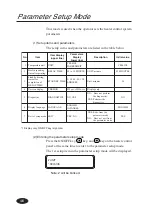
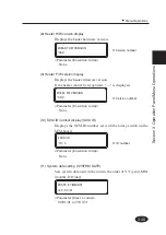
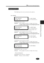
background image

4-4

LCD Display

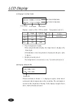
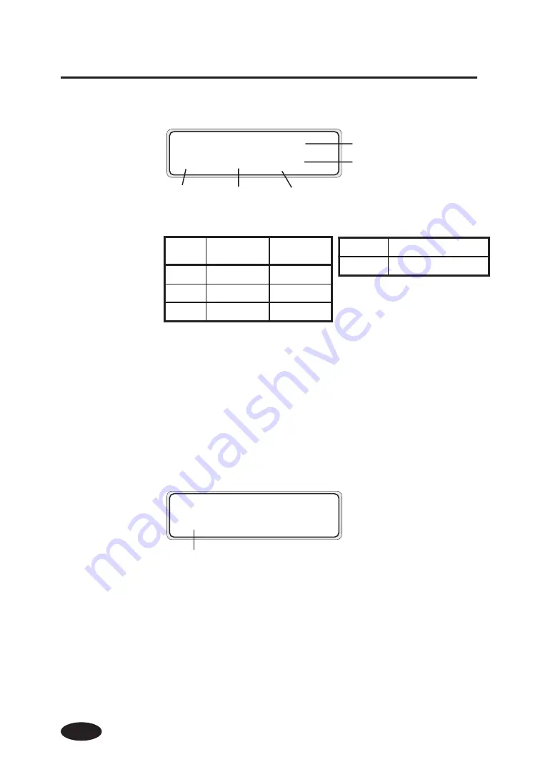
(1) Display in normal mode

Display: (AAA to CCC, YYY to ZZZ)

Temperature unit: (U)

• Preset temperature display

When using fahrenheit display, the temperature is displayed by

three digits.

(99 fahrenheit or less temperature is displayed with space ;plus

2 digits.)

• Display renewal period

The temperature is measured at every 5 second and renewed.

AAAU  BBBU  CCCU

XXXU  YYYU  ZZZU

Heater

Setup

temperature

Current

temperature

FRONT

AAA

XXX

PRINT

BBB

YYY

REA

CCC

ZZZ

C

Celsius

F

Fahrenheit

Preset temperature

Current temperature

Front heater

Print heater

Rear heater

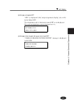
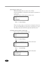
(2) Display at heater ON

When each heater is heated, “+” is displayed in place of the unit of
each heater current temperature on the second line. The unit display is
restored at the completion of heating. In the display example shown
above, the front heater is heated.

AAAU  BBBU  CCCU

XXX+  YYYU  ZZZU

Heater ON

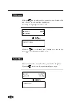
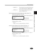
Summary of Contents for IP-6600

Page 1: ...de Solvent Ink Color Inkjet Printer IP 6600 Seiko I Infotech Inc Read this User s Guide to use the printer safely and properly Keep this manual in a place where you can quickly access it at any time U00086051203 ...

Page 2: ...re designed to provide reasonable protection against harmful interference when the equipment is operated in a commercial environment This equipment generates uses and can radiate radio frequency energy and if not installed and used in accordance with the instruction manual may cause harmful interference to radio communications Operation of this equipment in a residential area is likely to cause ha...

Page 3: ...describes the features of the printer names of components information to be known before use and basic operations such as how to turn the power on and off and set media and ink The following items should be read before reading Section 1 Deliverables Safety precautions Handling precautions Manual legend notation rules Read these items to use the printer safely and properly Keep this manual in a pla...

Page 4: ......

Page 5: ... the main unit on delivery Make sure that the following items are present If any parts are missing or damaged contact the shop where you purchased the product or the nearest service dealer Printer main unit 1 Built in SCSI interface Including a winding unit Basic components ...

Page 6: ...g liquid 100 ml Wiper cleaning liquid 100 ml Cleaning swab 50 pieces Syringe 10 pieces Starter kit 6 colors IP6 100 Y M C Bk Lc Lm 1 SCSI cable 1 Accessories screw driver for head up down adjustment Ink capacity of each ink cartridge for starter kit 6 colors IP6 100 is 500ml Approximately 100 ml ink for each color is consumed at initial ink charge Therefore this 100 ml ink for each color cannot be...

Page 7: ...o Print 4 Dx IP 540 1 PS RIP Photo Print 4 Server IP 541 1 Storage Kit IP6 137 1 set Maintenance liquid cartridge 6 Dummy cartridge 6 Cleaning Kit IP6 117 1 set Cleaning liquid cartridge 6 Dummy cartridge 6 Cap cleaning liquid 6 bottles IP6 138 1 set Cap cleaning liquid 100ml 6 bottles Wiper cleaning liquid 6 bottles IP6 139 1 set Cleaning swab IP6 147 300 pieces Waste ink bottle IP6 109 1 Ink car...

Page 8: ...in this manual to ensure the proper use of the printer and to prevent the printer from being damaged Follow the instructions marked with these symbols Minor personal injury or product and or peripheral damage Failure to follow the guidelines marked with this symbol could result in minor personal injury or product and or peripheral damage Serious personal injury or death Failure to follow the guide...

Page 9: ...cause fire or electric shock NEVER use the printer in a place of extreme humidity or any place where it can possibly be splashed by any liquids If any liquids get into the printer it could lead to fire electric shock or other serious accidents DO NOT remove the covers attached to the printer because they contain high voltage and extremely hot parts Careless removal might result in an electric shoc...

Page 10: ...printer stained with ink The coating of the printer may be damaged The ink used for the device contains organic solvent Ethylenglycolmonbutyleteracetat Therefore observe the local rules strictly related to organic solvent stuff The ink used for the device contains organic solvent Ethylenglycolmonobutyletheracetat Since the ink is flammable never use fire when using the device Do not swallow ink or...

Page 11: ...which could lead to electric shock and or fire DO NOT get ink on your skin or clothes Wash off any ink immediately with soapy water DO NOT put any paper rolls on an unstable table or a tilted surface as they could fall leading to an injury The heater will be hot Pay attention not to touch and not to be burned In order to ensure the safe operation of the printer heed all of the cautions and warning...

Page 12: ... turn the printer off 4 Do not clean the surface of the cover with benzene or paint thinner The coating may come off or deteriorate Wipe the cover clean with a soft cloth If the cover is very dirty use a cloth moistened with a neutral detergent 5 Do not touch the ink jet head surface Regular Inspection and Maintenance The following regular inspection and maintenance must be performed in terms of c...

Page 13: ... ink bottles 4 Do not get ink on your skin or clothes Wash off any ink immediately with soapy water 5 Check waste ink bottle regularly so as not to leak the waste ink 6 When the waste ink bottle is installed or removed spread the stain preventing sheet so as not to stain the floor with spilt ink 7 Store ink in a dark and cool place NEVER store ink in a high temperature or direct sunshining place D...

Page 14: ...damage to the printer Boxes marked with a note describe precautions while handling the printer HINT Hint mark The hint symbol describes operations that make using or handling the printer easier Reference mark This mark is followed by a reference section or page number Manual Legend Notational rules This manual uses the notational rules for marks keys LCDs and LEDs NOTE HINT WARNING CAUTION ...

Page 15: ...ts a key on the operation panel This represents the LC display on the operation panel On Flashing Off Example 2 LED s states in the text LED s states of On flashing and Off are characterized by the following symbols Example 1 Keys and messages shown on the LCDs in the text INK ENTRY PAPER F ADJ SERVICE FEED CLEANING FUNC SYSTEM ADJUST RESET This represents a key to seledt the menu Ex key Notation ...

Page 16: ...ons and key operations in the text A key on the operation panel This indicates that the LCD screen changes to another automatically without pressing a key This shows that the LCD screen changes to another when the operator presses a key INITIALIZING WAIT A MOMENT SERVICE FEED CLEANING ...

Page 17: ...ons 1 3 Consumables 1 5 Media Paper 1 5 Ink 1 8 Waste Ink Bottle 1 10 Maintenance Kit 1 11 Cap Cleaning Liquid 6 Bottles 1 12 Wiper Cleaning Liquid 6 Bottles 1 12 Cleaning Swab 1 12 Storage Kit 1 12 Cleaning Kit 1 12 External Views Part Names and Functions 1 13 Front 1 13 Rear 1 14 Heater 1 15 Operation Panel 1 16 Heater Control Panel 1 18 Dryer 64 Option 1 19 Roll Cover 64 Option 1 19 Exhaust Att...

Page 18: ...ing the Paper Roll 2 11 Installing Paper Roll in the Printer 2 11 Removing the Paper Roll from the Printer 2 17 Replacing Paper Roll with Another 2 18 Replacing Empty Paper Roll 2 18 Replacing Jammed Paper Roll 2 18 Installing Removing Cut Sheet in from the Printer 2 19 Paper Feed Adjustment Correction Value Setting 2 19 Change during online printing 2 24 Head print position adjustment 2 24 Replac...

Page 19: ...a Pressure Alternation Lever 2 56 Using the Head Up Down Lever 2 57 Using the Media Edge Guard 2 59 Using the FAN Guard Slide Lever 2 60 Using the Print Pause Restart and Cancel Keys 2 61 Inspection Maintenance 2 62 Section 3 Operation Panel Menu Operations 3 1 Basic Menu Operation 3 2 Menu Hierarchical Structure 3 2 Menu Tree 3 3 Basic Operations and Keys 3 8 Operation Procedure for Choice Input ...

Page 20: ...shooting 5 1 Troubleshooting 5 2 Clearing Paper Jam 5 3 When an Error Message Appears 5 4 Service Call Errors 5 4 Communication Errors 5 6 Operator Call Errors 5 7 When the Printer Fails to Work Correctly 5 11 When a Print Error Occurs 5 12 When There Is an Abnormal Sound 5 13 Appendix A 1 Basic Specifications A 2 Printer Specifications A 2 Options Consumables A 3 Options A 3 Consumables A 4 Celsi...

Page 21: ...ance Liquid Cartridge External Views Names of Parts and Functions Front Rear Heater Operation Panel Heater Control Panel Dryer 64 Roll Cover 64 Exhaust Attachment PS RIP PhotoPrint 4 DX PS RIP PhotoPrint 4 Server LCD Messages and Printer State Messages on the LCD F W Version Checking Method F W Version Checking Method Added Functions in V2 00 This section provides necessary information to operate ...

Page 22: ...567890123456789012345678901212345678901234 1234567890123456789012345678901212345678901234 1234567890123456789012345678901212345678901234 1234567890123456789012345678901212345678901234 1234567890123456789012345678901212345678901234 1234567890123456789012345678901212345678901234 1234567890123456789012345678901212345678901234 1234567890123456789012345678901212345678901234 1234567890123456789012345678...

Page 23: ...midity 30 to 70 To obtain better print quality use the printer within temperatures of 20 to 25 C When operating temperature is lower than 20 C the print speed goes down two third of normal print speed to keep a good print quality When the head temperature goes high the print time is delayed HINT NOTE When the printer is used out of range of the operating temperature and humidity the print may be s...

Page 24: ... subject to vibration Places with excessive dust Places subject to extreme changes in temperature or humidity Places near an air conditioner or a heater Places where the printer may get wet Places subject to direct air circulation from vents Places near a diazo copier that may generate ammonia gas Places with poor ventilation Unstable places ...

Page 25: ... 1 Getting Started Basic knowledge Media Paper Available media types We prepared the following types of media Glossy vinyle chrolide Matted vinyle chrolide Banner Contact our service center for details Consumables ...

Page 26: ...ture and humidity after opening package Set media after leaving media in the operation environment for 3 hours or more Use care for a change of humidity by turning ON OFF the air conditioner In terms of media characteristics curl of paper in low humidity and wrinkle of media in high humidity may occur easily Use paper in normal temperature and humidity environment around 23 C and 50 RH Do not use ...

Page 27: ...or laser prints to prevent sticking due to ink or toner Do not rub scratch or hold the media to prevent pealing Do not rub or leave the paper in wet condition to prevent blurring Other precautions Media causes color fading and a change in quality in getting old Check paper condition and use well conditioned paper Paper dust due to cutting may cause float of coating When using vinyl with glue adhes...

Page 28: ...e ink is 12 months after the manufacture date Do not shake ink cartridges before use All six color cartridges must be installed If any of the cartridges is removed a new one must be installed o N m e t I r o l o c k n I y t i c a p a c k n I 1 0 1 6 P I w o l l e Y Y l m 0 0 0 1 2 0 1 6 P I a t n e g a M M l m 0 0 0 1 3 0 1 6 P I n a y C C l m 0 0 0 1 4 0 1 6 P I k c a l B k B l m 0 0 0 1 5 0 1 6 ...

Page 29: ...r the printer may malfunction Store ink cartridges in a dry cool and dark place Always use the recommended consumables paper ink etc Failure to follow this instruction may cause poor print quality or a breakdown Never bring the ink close to fire Failure to follow this warning might result in fire Do not swallow ink or avoid its splashes on the eye If it gets into the eye wash it off with a clean r...

Page 30: ...nsult a doctor as required If it is swallowed do not try to vomit it forcefully but see a doctor Install the waste ink bottle securely A waste ink bottle must always be installed If it is removed for replacement a new one must be installed CAUTION NOTE Never put the waste ink bottle near open flames Failure to follow this warning might result in fire o N m e t I s k r a m e R 9 0 1 6 P I e c e i p...

Page 31: ... i n a e l c p a C l m 0 0 1 d i u q i l g n i n a e l c r e p i W l m 0 0 1 b a w s g n i n a e l C s e c e i p 0 5 e g n i r y S s e c e i p 0 1 Precautions for handling the waste ink bottle After use securely fasten the attached cap and dispose of this product as industrial waste If you have any questions please contact your nearest sales office CAUTION Do not swallow ink or avoid its splashes ...

Page 32: ... IP6 107 6 Dummy cartridge IP6 118 6 o N m e t I s k r a m e R y t i t n a u Q 8 3 1 6 P I l m 0 0 1 d i u q i l g n i n a e l c p a C 6 Cap Cleaning Liquid 6 Bottles Wiper Cleaning Liquid 6 Bottles o N m e t I s k r a m e R y t i t n a u Q 9 3 1 6 P I l m 0 0 1 d i u q i l g n i n a e l c r e p i W 6 g n i r y S 0 1 Cleaning Swab o N m e t I s k r a m e R 7 4 1 6 P I s e c e i p 0 0 3 ...

Page 33: ...tting heater temperature are located on the heater control panel 3 Ink holder Holds the ink cartridge 4 Flange Sets paper roll 5 Caster Unlocks the caster to move the printer and lock it to secure the printer 6 Paper pressure alternation lever Alternates paper pressure depending on the paper thickness 7 Pressure roller up down lever Presses down the paper after inserting the paper into the paper s...

Page 34: ... 10 Printer switch 11 Rear cover 12 SCSI connector 13 ID switch SCSI controller 14 Terminator switch 15 Paper outlet 16 Waste ink bottle 17 Power receptacle 18 Heater switch 19 100 V 200 V alternation switch 20 Cap cover 21 Wiper cover 22 Print stop restart cancel keys 23 FAN guard potitioning slide bar 24 Head up down lever ...

Page 35: ...nt heater Rear Infiltrates ink into the paper and fixes ink 27 Rear heater Finish Drys ink and stabilizes print image Three heaters are controlled separately WARNING Heaters become hot NEVER touch the heaters If doing so it could lead to burn External Views Part Names and Functions Front Paper roll Paper inlet Rear Rear cover Paper outlet paper feed direction 25 26 27 Grid roller Pressure roller ...

Page 36: ... panel as follows It has a buzzer to alert errors or invalid key operations 3 Power switch Turns the printer ON or OFF 2 Keys Used to set printer functions 4 LCD Shows the printer status and menus 1 LED The LEDs light flash or turn off to the status of the printer B C D E A ...

Page 37: ...ws whether paper is set On Paper is set Roll paper or cut sheet is set Off No paper Neither roll paper nor cut sheet is set E Online LED green Shows whether the printer is online or offline On Online Flashing Online pause mode Off Offline 2 Key ONLINE key Switches between online and offline states SHIFT Key Used as an auxiliary key for parameter input switches the menu level display CANCEL Key Can...

Page 38: ...t n e h W R A E R r a e r e h t f o e r u t a r e p m e t t n e r r u c e h t d n a e r u t a r e p m e t g n i t t e s e h t s e t a c i d n I o t d e g r u s i t i f f o d e n r u t s i r e t a e h e h t f o h c t i w s n i a m e h t n e h W r e t a e h h c t i w s n i a m e h t n o n r u t d e t a c i d n i s i F F O f f o d e n r u t s i r e t a e h r a e r e h t n e h W y e k F F O N O T N O ...

Page 39: ... output media Roll Cover 64 Option Protects paper roll from dust Exhaust Attachment Option Mounts an exhaust gas pipe to the printer or the drying device PS RIP PhotoPrint 4 DX Option PS RIP PhotoPrint 4 Server Option RIP software for the IP 6600 External Views Part Names and Functions ...

Page 40: ... The printer is being initialized Booting When the system starts normally both controllers go online and enter idle mode automatically 2 Online state idle mode display The printer can receive data from the computer PRINT READY ROLL 64 PAPER Status display Paper information INITIALIZING WAIT A MOMENT When the key is pressed in the menu mode CLEANING menu appears ...

Page 41: ...formation LCD Messages and Printer State 4 Online state print pause mode display The printer is paused Print stop and resume The ONLINE LED flashes Press the key in the print pause mode to start the head cleaning Print cancel end The ONLINE LED flashes PRINT READY ROLL 64 PAPER PRINT READY ROLL 64 PAPER PRINT READY ROLL 64 PAPER PRINTING ROLL 64 PAPER ...

Page 42: ... and ink removing amount are displayed Bk INK REST XXX Lm INK REST XXX PRINT READY ROLL 64 COATED Lc INK REST XXX Y INK REST XXX Three second intervals or Three second intervals or Then the printer returns to online idle mode TOTAL CT XXXX M INK REST XXX C INK REST XXX ...

Page 43: ...tting down SHUTDOWN WAIT A MOMENT 6 Offline menu mode display Menus can be operated in offline mode and are access keys to menus When the key is pressed in the menu mode CLEANING menu appears SERVICE FEED CLEANING FUNC SYSTEM ADJUST RESET LCD Messages and Printer State INK ENTRY PAPER F ADJ ...

Page 44: ... F ADJ FUNC SYSTEM ADJUST RESET F W VERSION X XX_YY 1 History print The function that prints the maintenance history was added 2 Paper feed adjustment During the online print the paper feed adjustment correction value can be changed temporarily with keys 3 Media entry The registered media information can be copied to a new area 4 Waste ink value saving The mode that saves the waste ink quantity du...

Page 45: ...dge Replacement Procedure Replacing Empty Ink Cartridge If an Ink Cartridge Is Not Installed Replacing Cartridges during Printing If an Ink Cartridge Is Not Detected Replacing the Waste Ink Bottle Waste Ink Bottle Replacement Procedure If the Waste Ink Bottle Is Full If the Waste Ink Bottle Is Not Installed Head Cleaning CLEANING Paper Feed FEED Using the Origin Point Setting Function Installing P...

Page 46: ...following connection is possible Connection procedure Connect a cable as follows 1 Turn the printer and the computer OFF Printer Printer server PostScript RIP SCSI interface NOTE When the printer is connected with the computer turn the printer ON and then turn the computer ON To turn the system OFF turn the computer OFF and then turn the printer OFF ...

Page 47: ...E Use a dedicated SCSI cable 68 68 pin 6 m If using a cable except the specified one the printer can not satisfy FCC and CE regulations ID switch Set the ID number with a small normal driver etc Initial ID value 4 2 Connect a SCSI cable to a SCSI connector on the rear of the printer It can be connected to any one of two SCSI connectors Connecting with Computer NOTE ...

Page 48: ...as the SCSI terminator ON OFF function If the external terminator is not used and the printer is a terminating device in the SCSI chain only one SCSI connector is connected set the terminator switch to ON If the printer is not a terminating device set it to OFF Terminator switch ...

Page 49: ...switch on the operation panel Heater The heater has two power switches as follows 1 Heater switch 2 100 200 V alternation switch Printer rear Right side NOTE When the printer is connected with the computer turn the printer ON and then turn the computer ON To turn the system OFF turn the computer OFF and then turn the printer OFF Turn the computer ON after the printer becomes to the online state 1 ...

Page 50: ... OFF 0 the printer switch on the left rear of the printer and plug one end of the supplied power cable into the socket of the printer Insert the other power plug of the cable into an electrical outlet 2 Turn ON 1 the printer switch on the left rear of the printer Printer switch OFF 0 Socket Printer switch ON 1 Socket ...

Page 51: ...e heater power ON to use the heater When the heater power is turned OFF the following message is displayed on the heater control panel TURN ON THE HEATER If the fan does not run or the operation panel lamp does not light when the printer switch and power ON OFF switch on the operational panel are turned ON the power supply may be faulty If an error is detected during the self diagnostic test at po...

Page 52: ... switch on the right rear of the printer to turn the heater ON Heater switch OFF 0 Power socket Power cable Heater switch ON 1 100 200 V alternation switch 100 200 V alternation switch Do not use the other power cable than specified in this printer Verify that the supplied power cable meets the local AC power supply specifications Verify that the 100 200 V alternation switch settings meets the loc...

Page 53: ...ssing the power ON OFF key while pressing the key Performing the fill cap operation is recommended The printer switch on the rear of the printer should be used only when the printer is turned OFF completely in order to move it connect it with a computer install or maintain its parts Turn the power ON OFF switch OFF wait for at least ten seconds then turn it ON again The printer performs fill cap o...

Page 54: ...N OFF switch on the operation panel Therefore the heater switch turning OFF operation is not necessary in the normal use Use the heater switch on the right rear of the printer only when turning the printer OFF completely for transferring installing and maintenance service of the printer NOTE ...

Page 55: ...is replaced when it jams A paper replacement procedure in each case is explained below Installing Paper Roll in the Printer 1 Open the rear cover and slide the media edge guards to the both edge of the platen 2 Insert the paper roll in the paper roll right flange fix side Paper roll Right flange fixed Be sure not to damage the edge of the paper roll when inserting the paper roll in the flange NOTE...

Page 56: ... front side 5 Lift the pressure roller up down lever Left flange knob Winder sensor lever Pressure up down lever Paper roll Left flange movable Be sure not to catch your finger in the rail of the flange CAUTION 3 Slide the left flange movable side and put it into the paper roll ...

Page 57: ...aper goes out 200 mm or more from the paper outlet Paper may stick to the paper feeder and is hard to set due to operational condition especially low humidity In such a case float paper from the paper feeder and set paper to the paper feeder by holding both edges of the paper Be sure not to hit the edge of the paper roll by the rear cover Be sure that the media edge guard is not set under the pape...

Page 58: ...e inserted in the right of the perforated line If the paper roll is inserted in the right of the perforated line adjust the flange position 8 Push down the pressure roller up down lever Perform operations according to the guidance message shown on the LCD Pressure up down lever 9 Confirm the media edge guard setting again Confirm whether the media edge guard does not goes down of the paper Confirm...

Page 59: ...gistering a new paper type SELECT PAPERTYPE PAPER PAPER Select a paper type with and keys 11 Select a paper type Select paper type with or key Press the key to change setting Press the key to leave the setting as it is SELECT PAPERTYPE PAPER PAPER SELECT PAPERTYPE PAPER XXX Press key to enter to NEW PAPER ENTRY menu Operation of the new paper entry is the same as operation for paper entry from ENT...

Page 60: ...rs an error message will be displayed Go back to 1 12 The paper will be set automatically 13 Determine the position of movable fan After the paper setting operation finished adjust the position of the fan guard slide lever at the rear of the printer See Using the fan guard slide lever P 2 60 Fan guard slide lever ...

Page 61: ...inter 1 Lift the pressure roller up down lever 2 Loose the left flange knob pull out the paper roll from the flange and remove the paper roll from the printer Pressure roller up down lever Left flange Paper roll Right flange Flange knob 2 3 1 4 Replacing the Paper Roll ...

Page 62: ... Paper Roll in the Printer and Removing it from The Printer Replacing Empty Paper Roll 1 A message appears on the LCD 2 Replace the paper according to the Installing Paper Roll in the Printer and Removing it from the Printer LIFT LEVER SET PAPER Replacing Jammed Paper Roll See the Cleaning Paper Jam in Section 5 Troubleshooting LIFT LEVER INK ENTRY PAPER F FDJ ...

Page 63: ...e paper of width larger than A1 size and length longer than 1m Press the key For the paper feed correction obtain approximate paper feed adjustment correction value in the ROUGH mode and set exact correction value in the DETAIL mode One printing requires the paper length of 48 to 58 cm in the ROUGH mode or 27 to 32 cm in the DETAIL mode Printing of paper feed adjustment pattern can be cancelled by...

Page 64: ...ult select approximate paper feed adjustment correction value As nine patterns are printed in steps of 0 25 in a range of 99 00 to 101 00 select approximate correction value Select the print mode you usually use for the paper to which the paper feed adjustment correction value is set Selectable print modes are Standard High Quality High Density High Speed and Draft Select the paper feed adjustment...

Page 65: ...d adjustment pattern FEED PATTERN ROUGH NORMAL 10 Press the key to select a print mode for the DETAIL pattern Select the same print mode as that for the ROUGH pattern FEED PATTERN DETAIL NORMAL 11 Press the key twice to print the paper feed adjustment pattern DETAIL FEED PATTERN EXECUTING 12 From the printed result select exact paper feed adjustment correction value As five patterns are printed fo...

Page 66: ...ED ADJUST 099 80 14 Enter the paper feed adjustment correction value and press the key Adjust the place with key and set a numeric value with key 15 Press the key and then the key to display the paper feed adjustment pattern FEED PATTERN DETAIL NORMAL 16 Press the key to return to the initial OFFLINE state ...

Page 67: ...alue is appropriate if the joints of pass lines are not overlapped but uniform Correction value is large if the joints of pass lines are separated become light NOTE Set average value if appropriate correction value is different every head every color However if an image to be printed has a preferential color set correction value of that color Set average value if appropriate correction value is di...

Page 68: ... selected paper feed adjusting value On the right side of the first row the value at the start of print is displayed and it does not vary until the print finished However if a cleaning is executed in the MODE 2 in the midway of operation the changed value is displayed after the cleaning With the or key increase or decrease the value in a step of 0 01 When the value is changed it is reflected in th...

Page 69: ...ey 2 Press the key twice to display ADJUST 3 Press the key and then the key to display ADJUST PATTERN 4 Press the key and select HEAD ADJ1 and then press the key 5 If the key is pressed the HEAD ADJ1 of adjustment patterns is printed INK ENTRY PAPER F ADJ FUNK SYSTEM ADJUST RESET ADJUST PATTERN TEST PRINT ADJUST PATTERN HEAD ADJ 1 OK ADJUST PATTERN EXECUTING Replacing the Paper Roll ...

Page 70: ...2 26 Head position adjustment Left and Right Head position adjustment Reciprocating position adjustment R Reciprocating position adjustment L Paper discharge direction ...

Page 71: ...head position adjustment of the HEAD ADJ1 patterns enter a numeric value of the fittest pattern Select the digit to be entered between and with keys and change value with keys 4 Press the key L R ADJ Bk 00 A L R ADJ Y 00 A Replacing the Paper Roll 21 8 Find a head adjustment sample where 2 lines with the same color are aligned In case of Y head illustrated in the right for instance 21 shows the sa...

Page 72: ...head position adjustment of the HEAD ADJ1 patterns enter a numeric value of the fittest pattern Select the digit to be entered between and with keys and change value with keys 4 Press the key H POS ADJ Lm 00 A H POS ADJ Lc 00 A 21 2 Find a head adjustment sample where the BK head line and the head position are aligned In case of LC head illustrated in the right for instance 21 shows the sample whe...

Page 73: ...e key to display the head to be adjusted and press the key 3 Of the reciprocating print position Left adjustment of the HEAD ADJ1 patterns enter a numeric value of the fittest pattern Select the digit to be entered between and with keys and change value with keys For a hint on how to locate an appropriate adjustment value refer to 2 Head Right and Left Adjustment on page 2 27 4 Press the key I POS...

Page 74: ... the key to display the head to be adjusted and press the key 3 Of the reciprocating head position Right adjustment of the HEAD ADJ1 patterns enter a numeric value of the fittest pattern Select the digit to be entered between and with keys and change value with keys For a hint on how to locate an appropriate adjustment value refer to 2 Head Right and Left Adjustment on page 2 27 4 Press the key I ...

Page 75: ... 1 Open the ink cover Ink cartridge Do not remove an ink cartridge under the following conditions Depending on the printer status the ink spills within the ink box causing a trouble In case that no power is supplied to the printer because of a power failure or printer breaker off In case that an error other than ink end has occurred If the cartridge in which the ink remains is replaced do so in th...

Page 76: ...ver 5 End of ink cartridge replacement If it is ended normally return to offline or online state If abnormal end occurs an error message will be displayed Go back to 1 The printer continues to print when the ink remains in the sub tank during replacing ink cartridge New ink cartridge Ink cover Ink cover Ink cover ...

Page 77: ...ce message appears 2 Replace the ink cartridge according to the Ink Cartridge Replacement Procedure OPEN R INKCOVER CHANGE XX INK XX Ink name C CYAN M MAGENTA Y YELLOW OPEN L INKCOVER CHANGE XX INK XX Ink name Bk BLACK Lm LIGHT MAGENTA Lc LIGHT CYAN Replacing Ink Cartridges ...

Page 78: ...guidance message appears 2 Replace the ink cartridge according to the Ink Cartridge Replacement Procedure OPEN R INKCOVER SET XX INK XX Ink name C CYAN M MAGENTA Y YELLOW OPEN L INKCOVER SET XX INK XX Ink name Bk BLACK Lm LIGHT MAGENTA Lc LIGHT CYAN ...

Page 79: ... The guidance that prompts you to close the ink cover is displayed on the second line of LCD The printing operation continues if the ink is present in the sub tank even though the ink cover is open However no ink is supplied to the sub tank because the ink cover is open If the ink in the sub tank is used up the print pause mode is activated and the printing operation is interrupted until the ink c...

Page 80: ...the sub tank was used up the print pause mode is activated and the printing operation is interrupted until the main cartridge is replaced To recover from the interrupted state close the ink cover and press the ONLINE key and the pause mode is then cancelled and the print will restart PRINTING ROLL 64 PAPER PRINTING OPEN X INKCOVER PRINTING CHANGE YY INK XXXX L R YY Bk Lm Lc Y M C The guidance conc...

Page 81: ...idance message appears 2 Replace the ink cartridge according to the Ink Cartridge Replacement Procedure OPEN R INKCOVER CHECK XX INK XX Ink name C CYAN M MAGENTA Y YELLOW OPEN L INK COVER CHECK XX INK XX Ink name Bk BLACK Lm LIGHT MAGENTA Lc LIGHT CYAN Replacing Ink Cartridges ...

Page 82: ...bottle replacement procedures for these cases are explained below Do not replace the waste ink bottle during printing Waste Ink Bottle Replacement Procedure 1 Loosen the knob and lift up the lever from the waste ink bottle 2 Wait for a while to drop the remaining ink into the ink tube 3 Take out the filled waste ink bottle from the printer and securely cap the waste ink bottle to replace with a ne...

Page 83: ...ever and mount a new waste ink bottle 6 Drop the lever and insert the ink tube securely and tighten the knob 7 The selection message of the waste ink counter setting reset clear will be displayed 8 Select YES and press the key INK COUNT RESET NO INK COUNT RESET YES 1 2 Replacing the Waste Ink Bottle ...

Page 84: ... counts up from the empty of the waste ink bottle Always select YES for the INK COUTN RESET menu when replacing the waste ink bottle with a new one If not the waste ink full counter cannot be only used effectively but also the waste ink becomes full before generating warning and the waste ink may be spilt over 3 Select YES and press the key INK COUNT RESET NO INK COUNT RESET YES NOTE If the Waste ...

Page 85: ... bottle into the printer and install the waste ink bottle cover See the step 3 of the Waste Ink Bottle Replacement Procedure 3 The selection message of the waste ink counter setting rest clear will be displayed 4 Select YES and press the key BOTTLE ISN T SET SET BOTTLE INK COUNT RESET NO INK COUNT RESET YES Replacing the Waste Ink Bottle ...

Page 86: ...to display the CLEANING menu 3 Press the key to enter the head cleaning menu 4 Press the key INK ENTRY PAPER F ADJ INK ENTRY PAPER F ADJ SERVICE FEED CLEANING CLEANING NORMAL CLEANING OK 5 Press the key and key to select a cleaning option CLEANING NORMAL CLEANING SLIGHT CLEANING STRONG ...

Page 87: ... key again NOTE The cleaning takes several minutes 8 When the cleaning is completed the screen is retured to step 3 automatically 9 Press the key to return to the original offline mode CLEANING WAIT A MOMENT XXX CLEANING NORMAL XXX Figure will be increased in about 10 seconds CLEANING BOTTLE OK Head Cleaning CLEANING ...

Page 88: ... the key to display the FEED menu 3 Hold down the key While the key is kept pressed the currently selected roll paper is fed If a cut sheet is used it is discharged 4 When the key is released paper feeding stops and the top screen returns to offline mode PAPER FEEDING SERVICE FEED CLEANING SERVICE FEED CLEANING INK ENTRY PAPER F ADJ ...

Page 89: ...nt to print an image on the blank area The print origin point setting at paper rewinding is called as Origin Point Setting Function 1st time printing Paper rewinding 2nd time printing How to Use the Origin Point Setting Function 1 Lift the pressure roller up down lever and rewind the paper Rewind the paper after the paper is enoughly dried If not the 1st time printing image may be damaged SET PAPE...

Page 90: ... origin point The previous setting value will be displayed PAPER WIDTH 1372 mm BASE POINT 0000 mm SELECT PAPER ROLL SHEET BASE Pressure roller up down lever The paper width detected at previous time is displayed Paper width input range 290 to 1635 mm The base point set at previous time is displayed The origin moves if either paper width or base point is set Print margin Base point input value Pape...

Page 91: ...EED BACK NO PAPER FEED BACK YES The area from the paper output sensor position to the print start position the grid roller becomes print dead area The print dead area can be decreased by rewinding the paper for length between the paper output sensor and grid roller 20 to 30 mm from the front edge cannot be printed 6 Select Yes or No of back feed operation NOTE Cut the edge of the paper so that it ...

Page 92: ...be with the lead paper to the left flange Paper tube Tape Approx 1 m Paper tube Lead paper Pay attention to the direction of attaching tape on the winding side according to the winding direction setting outer side rewind inner side rewind Attach the paper to the take out roller straightly to protect slanting feed The paper tube width on the winding side must be same as the width of the rolled pape...

Page 93: ...panel see Section 3 Operation Panel Menu Operations Feed Menu until the paper is wound Paper feeder Paper delivery unit rear 4 Tighten the right flange knob securely Left flange Paper tube Right flange Paper tube Right flange Right flange 3 Slide the right flange movable side and insert it into the paper tube Paper tube Knob Pressure roller up down lever Pressure roller up down lever 2 1 3 Install...

Page 94: ... paper slightly 8 Check the positions of the paper and winding sensor and install it 6 Tape the edge of the paper on the lead paper at three positions both sides and center Paper tube Tape Tension roller Tension roller Paper Lead paper Tape Winding sensor Winder switch Right flange ...

Page 95: ... tension winding and slack winding Generally use the slack winding If the slack winding does not work correctly use the tension winding Also be sure to use the slack winding for glossy paper Also inner winding and outer winding are available Tension roller Tension roller Slide seven tension rollers according to the paper width To slide a tension roller loosen three slotted head screws Installing P...

Page 96: ...or printing surface may be damaged or be folded due to contact with the winding sensor caused by winds Fold the winding sensor or handle the printing surface with care In case that the paper roll for the winding unit exceeds the diameter of the winding unit s flange Winding unit switch setting Either internal winding or external winding can be selected When the winding unit is not used turn the wi...

Page 97: ...eater control panel ON OFF setting Use ON OFF key for each heater Temperature setting Use the up key or down key for each heater LCD screen When the heater is turned ON Upper line Preset temperature for each heater Lower line Current temperature for each heater When the heater is turned OFF Upper line OFF for each heater Lower line Current temperature for each heater The preset temperature range i...

Page 98: ...perature according to the paper type and environmental temperature When the print heater temperature is set to high the printer may print at low speed to ensure stable print quality Set the front rear heater temperature higher 5 C than the print heater s Bad temperature balance between the front rear heater and print heater may cause paper wrinkle m u i d e M e p y T a i d e M t e s e r p d e d n ...

Page 99: ...etting Heater set for the paper is Panel Priority The temperature set with RIP is ignored and the heating starts with the set temperature on the heater control panel 3 The print starts when the current temperature of front print and rear heaters all reaches the value exceeding set temperature 2 C the print starts If the current temperature is higher than the set temperature the print starts withou...

Page 100: ...ure When media cannot be fed correctly due to skew set the media alternation lever to high pressure Use the media pressure alternation lever to alternate the media gripping pressure See the figure below Normal pressure High pressure NOTE The shape of the lever groove is shown below Pull the lever front and push up the lever for alternate the pressure from high to normal 1 2 Paper pressure alternat...

Page 101: ...t the head up down lever up for glossy vinyle chloride and matted vinyle chloride and preset the head up down for banner and FF When the paper thickness is 0 5 mm or more preset the head up down lever up regardless of media type When the head is rubbed with the media due to media floating preset the head up down lever down even for the thinner media Head fixing screw Head up down lever Cap cover U...

Page 102: ...hand When the head height is changed change head height setting 19 in ENTER menu When the head height is changed print gap may be occurred at reciprocating print In that case adjust the correction value for reciprocating print See 20 Reciprocating print position Left adjustment value and 21 Reciprocating print position Right adjustment value in ENTRY nemu NOTE ...

Page 103: ... the media edge guard The right and left margin of the print area will be changed according to the setting of the edge guard When using the media edge guard right and left margin of the print area becomes 10 mm NOTE Mount the media edge guard on the right and left media transmission path to protect the head from nap and curl of the media edge Using the Media Edge Guard ...

Page 104: ...ording to the paper width you use When setting the FAN guard slide lever for 50 inch width paper at 64 inch width paper printing the paper cannot be passed Do not move the fan guard slide lever during print If the fan guard slide lever hits the paper paper jam could be occurred To prevent a jam due to the skew feed ensure a clearance of about 5mm between the arrow on the slide lever and the paper ...

Page 105: ...tlet side of the printer Print pause restart and print cancel are available during checking the print condition from the paper outlet side ONLINE key Pause Restart printing CANCEL key Cancels printing Operations of the ONLINE and CANCEL keys are the same as those of the operation panel s Rear PRINT Pause Restart and Cancel Keys Paper ONLINE key CANCEL key ...

Page 106: ...g Capping Unit Cleaning Waste Ink Bottle Disposal Soft Head Cleaning Test Print 2 63 2 Every one month inspection and maintenance Head cleaning 2 67 3 When leaving the printer for a long time in power off state more than 2 weeks Service Clean 2 67 4 When returning the printer from a long time leaving more than 2 weeks Head Wash Ink charge after head washing 2 68 5 When returning the printer from a...

Page 107: ... Waste Ink Bottle Disposal 5 Soft Head Cleaning 6 Test Print NOTE Wiper Blade Cleaning Enter to the SERVICE menu and select WIPE CLEANING on the operation panel The wiper blade will come up for cleaning Open the rear cover and the wiper cover WIPER CLEANING Rear cover Wiper cover Perform the above every day before print Always use our specified cleaning liquid and cleaning swab Inspection Maintena...

Page 108: ...r cleaning liquid to attach to the parts other than wiper blades Attaching the wiper cleaning liquid to the belts or sensors may cause a trouble Wiper blades NOTE Wiper Sponge Cleaning The wiper sponge has to be moistened Check the moisture of the sponge every day before printing Check whether the sponge is dried by pressing the dried swab on the sponge If the sponge is dried moisten it with the w...

Page 109: ...ICE menu and select CAP CLEANING on the operation panel The head carriage will move to the wipe side and you can access easily to the capping unit Open the rear cover and cap cover Wipe up the edge and periphery of the upper surface of all six caps carefully with the cleaning swab Close the cap cover and rear cover The head carriage will return to the capping unit position home position automatica...

Page 110: ...as the 1st time print on every day and especially after cap cleaning for head cleaning When the print dot off occurs at test print perform slight head cleaning in the CLEANING menu See page 2 42 Soft Head Cleaning Enter to the CLEANING menu and select SLIGHT on the operation panel See page 2 42 Do not leave the head carriage at the position other than on the capping unit for a long time more than ...

Page 111: ...quid cartridges and six dummy cartridges are mandatory Prepare the storage kit IP6 137 Six maintenance liquid cartridges IP6 107 and six dummy cartridges IP6 118 are packed together in the storage kit Six maintenance liquid cartridges are used up by one service clean Servce Clean Enter to the SERVICE menu and select SERVICE CLEAN After the service clean finished turn off the power with dummy cartr...

Page 112: ...g kit Six cleaning liquid cartridges are used up by one head wash Head Wash Select HEAD WASH in SERVICE menu on the operation panel After performing the head wash charge the ink See Ink Charge after Head Washing The printer performs fill cap operation to keep the good head condition at first 20 hours after print wait state and every 3 days It is recommended to keep the printer ON except when the p...

Page 113: ...than 200cc has been inserted replace it with the cartridge that contains the ink more than 200cc When returning the printer from a long time leaving within 2 weeks in power off state Head Wash Perform the cleaning of the head and ink path with cleaning liquid Six cleaning liquid cartridges and six dummy cartridges are mandatory Prepare the cleaning kit IP6 117 Six cleaning liquid cartridges IP6 11...

Page 114: ...performs fill cap operation to keep the good head condition at first 20 hours after print wait state and every 3 days It is recommended to keep the printer ON except when the printer is not used for a long time Avoid leaving the printer with no ink for one month or more for head protection Do not open and close the rear cover and do not lift and push down the levers during service cleaning and hea...

Page 115: ... with soft cloth soaked in the cleaning liquid Turn OFF the printer power switch before cleaning Do not blow off paper dust If doing so print quility gets bad influence NOTE NOTE Do not leave the printer without maintenance liquid charge more than 2 weeks in power off state for head protection When leaving the printer more than one month consult with shops or our nearest service office in advance ...

Page 116: ...edures 1 Open the rear cover and put a soft cloth on ink stained on the platen to infiltrate ink into the soft cloth Infiltrate ink into the soft cloth with care so as not to spread it 2 Wipe out the ink mark on the platen with a soft cloth moistened with alcohol Platen Soft cloth Ink Platen Soft cloth moistened with alcohol ...

Page 117: ...o vacuum holes on the platen wipe out ink clung to the holes with a commerically available mini cotton swab then wipe out again with a mini cotton swab moistened with alcohol Use a ø3 mm mini cotton swab Platen Mini cotton swab Inspection Maintenance ...

Page 118: ...operations Basic Menu Operation Menu Hierarchical Structure Menu Tree Basic Operations and Keys Operation Procedures for Choice Input Value Input Execution and Character Input Menu Operations INK Menu PAPER Menu ENTRY Menu F ADJ Menu SERVICE Menu CLEANING Menu FEED Menu FUNC Menu ADJUST Menu SYSTEM Menu RESET Menu Contents of This Section ...

Page 119: ...rarchical Structure The menu has the following hierarchical structures Menu group This menu is displayed at the first level Some menus have several sub menus Second level menus Sub menus of the menu group Parameters Select a selected menu item or enter a value There are three methods choice value entry and execution INK ENTRY PAPER F ADJ SERVICE FEED CLEANING FUNC SYSTEM ADJUST RESET ...

Page 120: ...ONDITION PASS 01 NONE Enter a choice NORMAL DEWITY FINE FAST DRAFT 1 Menu Tree Basic Menu Operation Execution form Display Execution form Display Enter a choice 01 to 20 Execution form Display Enter characters Enter a value 000 to 999 Enter a value 97 0 to 103 0 Enter a choice BI UNI Enter a choice NONE 2 hours 30 min 4 hours 1 hour 2 3 EDGE GUARD 01 USE PAPER FEED MODE 01 SEQUENCE 1 WINDER MODE 0...

Page 121: ...AL LOW Enter a choice NORMAL SAVING Enter a choice WAIT SKIP Enter a value 15 to 55 Enter a value 15 to 55 Enter a choice NORMAL HIGHLIGHT Enter a value 15 to 55 Enter a choice NORMAL HIGH I POS L ADJ YY 01 00 A Enter a value 32 to 31 a to H YY Bk Lm Lc Y M C 4 3 CLEANING MODE 01 MODE 1 Enter a choice MODE 1 MODE 2 BACK ADJUST 01 0000 PULSE Enter a value 2000 I POS R ADJ YY 01 00 A Enter a value 3...

Page 122: ... a choice SERVICE CLEAN HEAD WASH INK CHARGE INK EXTRACT SERVICE FEED CLEANING Execution form Execution form Execution form BACK PATTERN NORMAL BACK ADJUST 0000 PULSE Enter a choice NORMAL H DENSITY H QUALITY DRAFT Enter a value 2000 ADJUST HEIGHT Execution form DLETE PAPER 02 TYOE02 OK Enter a value 01 to 20 COPY SOURCE 01 Enter a value 01 to 20 COPY DEST 01 01 Enter a value 01 to 20 PRIORITY MOD...

Page 123: ...D ADJ1 2 HEAD ADJ1 3 HEAD ADJ2 1 HEAD ADJ2 2 Enter a choice JAPANESE ENGLISH 7 5 Execution form Execution form Execution form Enter a value 32 to 31 A to H YY Bk Lm Lc Y M C Enter a value 32 to 31 A to H YY Bk Lm Lc Y M C Execution form Display BOOT VERSION X XX Execution form Display I POS R ADJ YY 00 A Enter a value 32 to 31 A to H YY Bk Lm Lc Y M C CLEANING NORMAL FEEDING Enter a choice NORMAL ...

Page 124: ...X Execution form Display ASIC VERSION X XX Execution form Display HEAT HW VERSION XX X Execution form Display HEAT FW VERSION XX X Execution form Display SCSI ID ID X Execution form Display DATE YY MM DD 03 08 01 Enter a value 00 01 01 to 99 12 31 SYSTEM TIME 00 00 Enter a value 00 00 to 23 59 INITIAL SET Execution form INITIALIZING WAIT A MOMENT Execution form ...

Page 125: ... menu group selection key Select a menu so that parameters can be changed 4 Parameter setting or change keys Switch between parameters Increment or decrement a value when it is entered keys Shift digit when entering a value 5 Parameter setting or canceling key Set a parameter key Cancel an input parameter value and return to the menu selection 6 Setting save The changes in the Setup menu System me...

Page 126: ... menu group with keys Select ENTRY menu with key 2 Select a sub menu of the ENTRY menu with and keys Select PRINT MODE You can return to 1 with key 3 Press key so that parameters can be changed 4 Select a parameter for the menu with and keys Select 01 FINE 5 Press key to change the parameter and return to 2 PRINT MODE 01 NORMAL PRINT MODE 01 NORMAL PRINT MODE 01 FINE PRINT MODE 01 FINE INK ENTRY P...

Page 127: ...enu with and keys Select PAPER FEED ADJ menu You can return to 1 with key 3 Press key so that parameters can be changed 4 Move to a digit to be modified with and keys PAPER FEED ADJ 099 80 PAPER FEED ADJ 099 80 PAPER FEED ADJ 099 80 5 Modify the value by pressing the and keys 6 Press key to change the parameter and return to 2 PAPER FEED ADJ 099 70 PAPER FEED ADJ 099 70 FUNC SYSTEM ADJUST RESET ...

Page 128: ...roup with keys Select FUNC menu with key 2 Select a sub menu of the FUNC menu with and keys Select MENU PRINT menu You can return to 1 with key 3 Press key 4 Press key to execute the function Press key to return to 2 without executing the function 5 After execution return to 2 MENU PRINT MENU PRINT OK MENU PRINT EXECUTING FUNC SYSTEM ADJUST RESET Basic Menu Operation ...

Page 129: ... menu group with keys Select SYSTEM menu with key 2 Select a sub menu of the SYSTEM menu with and keys When the SCSI ID is selected it is displayed 3 Another sub menu of the SYSTEM menu can be selected with and keys You can return to 1 with key SCSI ID ID x x SCSI ID number FUNC SYSTEM ADJUST RESET ...

Page 130: ... a sub menu of the ENTRY menu with and keys Select NAME 3 Press keys so that parameter can be changed 4 Select a character code group by pressing the and keys or and keys Modify the value by pressing the or key See Character List in the next page 5 Move to a digit by pressing the and keys Then modify the value INK ENTRY PAPER F ADJ NAME 01 TYPE01 NAME 01 CYPE01 NAME 01 CYPE01 NAME 01 TYPE01 Basic ...

Page 131: ...up Character Symbols space Numerals 0 to 9 Alphabet Capital letter A toZ Alphabet Small letter a to z Katakana line Katakana line Katakana line Katakana line Katakana line Katakana line Katakana line Katakana line Katakana line Katakana line Small letter katakana Special characters a ä b key key Character List ...

Page 132: ...mount of ink DATE indicates the manufacture date of the ink cartridge 2 When the key is pressed you can go to the next step without waiting for three seconds 3 When the or keys is pressed display scrolling ends and the top menu is displayed in offline state 4 When the key is pressed display scrolling ends and the printer is put online 5 When the key is pressed display scrolling ends and the printe...

Page 133: ... Paper width mm Z Paper length mm Base X Paper type Y Paper size 1 When the and keys are pressed display scrolling ends and the top menu is displayed in offline state 2 When the key is pressed display scrolling ends and the printer moves online state 3 When the key is pressed display scrolling ends and the printer enters paper setting sequence ROLL XXXXXX YYY INK ENTRY PAPER F ADJ Key SHEET XXXXXX...

Page 134: ...types from 01 to 20 can be selected Parameter Enter a choice Paper type number 01 to 20 2 Paper name setting NAME Set the paper name Six digit characters or symbols can be input as the paper name Symbols alphanumerals katakanas can be used for six digit characters Parameter Enter characters A six digit character symbols alphanumerals katakanas others SELECT PAPER 01 TYPE01 PAPER ENTRY PAPER F ADJ ...

Page 135: ... time SCAN WAIT TIME Unit second Set the paper scanning wait time Parameter Enter a value Input three digit in second unit 5 Print mode setting PRINT MODE Set a print mode Parameter Enter a choice NORMAL 4 pass FINE 8 pass DENSITY 8 pass FAST 4 pass DRAFT 2 pass FEED ADJUST 01 099 80 BASE 099 92 01 099 80 SCAN WAIT TIME 01 000sec PRINT MODE NORMAL ...

Page 136: ... according to the operational condition If there is no received data and the printer waits printing even though the specified time has passed the edge of the paper roll is fed to the front of the rear cover automatically If the edge of the paper roll exists in the front of the rear cover already this action will be skipped When the print data is received and print starts the conditioning pass the ...

Page 137: ...erformed at start of the printing Select this parameter when the printer prints in a high humidity environment frequently and the paper is extremely wrinkled 1 hour The conditioning pass is performed at every 1 hour Select this parameter when the print interval is more than 1 hour and the paper is extremely wrinkled 2 hours The conditioning pass is performed at every 2 hours Select this parameter ...

Page 138: ...per feed mode setting PAPER FEED MODE Set a paper feed mode Parameter Enter a choice SEQUENCE 1 Feeds the paper in the normal paper feed sequence SEQUENCE 2 Feeds the paper in the counter measure sequence for paper with glue 10 Winder mode WINDER MODE Set a paper winding mode Parameter Enter a choice SLACK Drives the winder with the SLACK rewinding method TENSION Drives the winder with the TENSION...

Page 139: ...etting the paper and then completes the paper setting after detecting the edge of the paper during paper rewinding Usually set NORMAL when selecting SAVING take care of the followings Cut the edge of the paper so that the edge of the paper is parallel to the guide line and set it to the printer If the edge of the paper is not parallel the print is missed on the edge of the paper and the platen is ...

Page 140: ...mperature reaches the preset temperature Parameter Enter a choice WAIT Waits the time until the heater temperature reaches the preset temperature SKIP Starts printing even if the heater temperature does not reach the preset temperature 14 Initial temperature setting for the front heater FRONT HEATER Sets the front heater temperature Celsius Fahrenheit Parameter Enter a value Range 15 C to 55 C The...

Page 141: ...e 15 C to 55 C The heater will be OFF when is set Celsius or Fahrenheiht display will be alternated on the heater panel The setting will be reflected at next powering on Celsius and Fahrenheiht conversion equation F 9 5 C 32 C 5 9 F 32 17 Color stripe setting COLOR STRIPE Sets ON OFF of the color stripe print Parameter Enter a choice OFF Does not print the color stripe at the origin point ON Print...

Page 142: ...color stripe is not set the print dot off may occur It is recommended to set the color stripe for printing if practicable NOTE If a pattern having very low printing rate in even one color is printed continuously at high temperature the print dot off may occur in low printing rate color In this case set the head mode to HILIGHT PRIORITY NOTE 19 Head height setting HEAD HEIGHT Selects a head height ...

Page 143: ...sitions Right for all heads I POS ADJ YY Enter an adjustment value based on the head adjustment pattern print YY Ink color Display order Bk Lm Lc Y M C Parameter Enter a value Sign Value 32 to 31 A to H A 0 8 B 1 8 H 7 8 20 Reciprocating print position Left adjustment Bk Lm Lc Y M C Adjusts reciprocating print positions Left for all heads I POS ADJ YY Enter an adjustment value based on the head ad...

Page 144: ...he printer works at mode 1 setting even if the mode 2 is selected When selecting mode 2 a joint of print will be generated because the cleaning is performed during print A joint can be adjusted with correction value input at BACK ADJUS menu In case a joint cannot be adjusted use mode 1 23 Paper back feed adjustment unit pulse Adjusts a joint position when the image is separated due to the automati...

Page 145: ... Parameter Enter a value DATA Gives priority to data PANEL Gives priority to the panel 27 Deleting registrated paper DELETE PAPER Deletes a registrated paper The registrated paper from 01 to 20 can be selected The registrated paper 01 is defined as the standard media This cannot be deleted When the key is pressed confirmation guidance will be displayed See below DELETE PAPER 01 TYPE02 DELETE PAPER...

Page 146: ...on copies already registered media information to copy the parameters in a set of the COPY DEST in 2 For further information see the description of parameter copy method Parameter choice input Paper No 01 20 However only the registered numbers are displayed 2 COPY DEST Select a copy destination for media registration Parameter choice input Paper No 01 20 The number already registered is attached w...

Page 147: ...t a copy source The parameter can be changed with the key For the copy source number only the registered numbers are displayed Press the key to determine the copy source parameter If the key is pressed in the midway of each menu operation the first menu comes back COPY SOURCE 01 COPY SOURCE 01 COPY SOURCE 13 COPY SOURCE 13 Key Key Key NOTE ...

Page 148: ...lready been registered is displayed following a numeral Press the key to determine the copy destination parameter If the copy destination is newly registered is not displayed following a numeral Press the key to execute the parameter copy operation If the key is pressed in the midway of each menu operation the first menu comes back COPY DEST 13 01 COPY DEST 13 01 COPY DEST 13 20 COPY DEST 13 20 OK...

Page 149: ... 1 E C N E U Q E S 1 E C N E U Q E S 1 E C N E U Q E S 1 E C N E U Q E S E D O M R E D N I W K C A L S K C A L S K C A L S K C A L S K C A L S E D O M T E S R E P A P L A M R O N L A M R O N L A M R O N L A M R O N L A M R O N M U U C A V L A M R O N L A M R O N L A M R O N L A M R O N L A M R O N R E T A E H T I A W T I A W T I A W T I A W T I A W T I A W R E T A E H T N O R F e n o N C 5 4 C 5 4...

Page 150: ...o the ENTRY menu 2 Select SELECT PAPER menu with the and keys 3 Press the key to change the parameter 4 Select a paper number to be registered with the and keys 5 Press the key to fix the paper number The display returns to 2 display INK ENTRY PAPER F ADJ SELECT PAPER 01 TYPE01 SELECT PAPER 01 TYPE01 SELECT PAPER 02 TYPE02 SELECT PAPER 02 TYPE02 Menu Operations ...

Page 151: ...d adjustment pattern 3 Press the key to display the massage This message will be displayed at new registration only 4 When the key is pressed the paper number 02 is registered newly and mark that shows the paper has already registered is displayed The display returns to 1 display Press the key to stop the new registration The display returns to 1 display FEED ADJUST 02 099 80 FEED ADJUST 02 099 80...

Page 152: ...d 101 0 and DETAIL that prints the paper feed amount adjustment pattern at every 0 06 step between current setting value 0 12 Obtain approximate value with the ROUGH parameter and determine the setting value with the DETAIL parameter Select a proper parameter according to the print mode Press the key during print to stop the print Parameter Enter a choice ROUGH NORMAL Select at adjustment in stand...

Page 153: ...int mode DETAIL H DENS Select at adjustment in high density print mode DETAIL DRAFT Select at adjustment in draft print mode 2 Paper feed correction value setting FEED ADJUST Sets the paper feed adjustment correction value Enter a correction value according to the paper feed adjustment pattern print The BASE value is displayed alternately on the 1st line Parameter Enter a value xxx xx 97 00 to 103...

Page 154: ...standard and high speed print modes H QUALITY Select at adjustment in high quality print mode H DENSITY Select at adjustment in high density print mode DRAFT Select at adjustment in draft print mode 4 Paper back feed correction value unit pulse Input a correction value of the paper back feed based on the result of the back pattern Parameter Enter a value 2000 pulse 5 mm 1 pulse 2 5µm BACK PATTERN ...

Page 155: ...ink is charged into the printer and then recharge the maintenance liquid in the printer to ensure long term storage Six maintenance liquid cartridges and six dummy cartridges are mandatory HEAD WASH Use this parameter to clean the head with the cleaning liquid with strong washing power at cleaning or service cleaning after long term time storage Six cleaning liquid cartridges and six dummy cartrid...

Page 156: ...Parameter Execution form None 4 Filling ink to the cap FILL CAP Fills the ink into the cap and soaks the head nozzle surface into the ink for 1 to 2 hours to remove the nozzle clogging Use this menu when the print off cannot be fixed by cleaning repeatedly Parameter Execution form None Always perform the cleaning normal after filling cap action If the print off cannot be corrected even leaving the...

Page 157: ...ight Use this at head height adjustment The cap is opened after performing this operation HEAD HEIGHT ADJUST HEIGHT OK ADJUST HEIGHT EXECUTING OPEN REAR COVER ADJUST HEIGHT Parameter Execution form None ADJUST HEIGHT ...

Page 158: ...blems such as a nozzle skip could occur depending on the data In such a case set the NORMAL mode CLEANING Menu This menu is used to clean the head of the printer When the key is pressed the cleaning menu will be operable Parameter Enter a choice NORMAL Cleans the head normally SLIGHT Cleans the head slightly STRONG Cleans the head strongly See Section 2 Head Cleaning for details SERVICE FEED CLEAN...

Page 159: ...MENU PRINT FUNC SYSTEM ADJUST RESET key PAPER FEEDING FEED Menu While the key is held down the currently selected paper roll is fed If a cut sheet is used it is discharged A feeding message appears on the LCD When the key is released paper feeding stops and the top menu appears on the LCD in offline mode SERVICE FEED CLEANING key ...

Page 160: ...og information print ERROR LOG PRINT Prints error log information saved in the printer Parameter execution form None 3 SCSI trace information print TRACE PRINT Prints SCSI protocol trace data It is printed only when the SCSI trace is set to ON Parameter execution form None 4 History print The maintenance data are printed Parameter execution form None HISTORY PRINT Additional functions available fr...

Page 161: ...nt can be stopped Parameter Enter a choices TEST PRINT Prints a block pattern with black and other color HEAD ADJ 1 Prints a head adjustment pattern HEAD ADJ 2 Prints a pattern for checking the head adjustment ADJUST 1 1 Prints only the left and right adjustment pattern of HEAD ADJ 1 ADJUST 1 2 Prints only the inter head position adjustment pattern of HEAD ADJ 1 ADJUST 1 3 Prints only the reciproc...

Page 162: ...nozzle Enter an adjustment value according to the head adjustment pattern YY Ink color Display order Bk Lm Lc Y M C Parameter Enter a value Sign Value 32 to 31 A to H A 0 8 B 1 8 H 7 8 3 Head position adjustment Lm Lc Y M C H POS ADJ YY Adjusts the head position for the scanning direction Enter an adjustment value according to the head adjustment pattern YY Ink color Display order Bk Lm Lc Y M C P...

Page 163: ...k Lm Lc Y M C Parameter Enter a value Sign Value 32 to 31 A to H A 0 8 B 1 8 H 7 8 5 Reciprocating position Right adjustment Bk Lm Lc Y M C Adjusts the head reciprocative position Right Enter an adjustment value according to the head adjustment pattern YY Ink color Display order Bk Lm Lc Y M C Parameter Enter a value Sign Value 32 to 31 A to H A 0 8 B 1 8 H 7 8 I POS L ADJ YY 00 A I POS R ADJ YY 0...

Page 164: ...layed on the LCD Parameter Enter a choice ENGLISH Displays English messages JAPANESE Displays Japanese messages 2 BOOT version display BOOT VERSION Displays the BOOT version Parameter Execution form None 3 F W version display F W VERSION Displays the engine firmware version Parameter Execution form None X System program version number Y Control number F W VERSION X XX_YY LANGUAGE JAPANESE FUNC SYS...

Page 165: ...ys the ICB board version Parameter Execution form None 6 ICB board version display ICB VERSION Displays the version number of the SCSI board WIM Parameter Execution form None 7 ASIC version display ASIC VERSION Displays the ASIC version Parameter Execution form None X Version number X Version number IPB VERSION X X WIM VERSION X X X Version number ICB VERSION X XX ASIC VERSION X XX X Version numbe...

Page 166: ...arameter Execution form None 10 SCSI ID number display SCSI ID Displays the SCSI ID number set with the rotary switch on the SCSI board Parameter Execution form None 11 System date setting SYSTEM DATE Sets system date used in the unit in the order of YY year MM month DD day Parameter Enter a value 00 01 01 to 99 12 31 X ID number SCSI ID ID X X Version number HEART HW VERSION XX X X Version number...

Page 167: ...ng SYSTEM TIME Sets system time used in the unit Parameter Enter a value 00 00 to 23 59 13 Factory setting INITIAL SET Sets all parameter values to factory settings Parameter Execution form None SYSTEM TIME 03 08 01 INITIAL SET ...

Page 168: ... the printer When the key is pressed the reset function is executed An initializing message appears on the LCD After resetting the printer goes online INITIALIZING WAIT A MOMENT FUNC SYSTEM ADJUST RESET key The set values including correction values are not cleared HINT Menu Operations ...

Page 169: ...Heater Controller Operation This section describes temperature control LCD displays param eter setup mode operations and error messages of the heater con troller Temperature Control LDC Display Parameter Setup Mode Error Messages Contents of This Section ...

Page 170: ...d the print start command is received 2 Under the condition 1 above in case of the time specified by the delay time after the print end command was received 2 Standby temperature maintaining condition Function To shorten time reaching the preset temperature at print start Status Status of maintaining the heater temperature at the specified standby temperature 35 C for all heaters When the preset t...

Page 171: ...rature Front heater preset temperature Standby temperature Environmental temperature Keeping of the preset temperature Keeping of the stand by temperature Keeping of the preset temperature Keeping of the stand by temperature Stop of the temperature control Print Print Delay time setting value Delay time setting value Standby setting time Standby setting time Time Temperature Start of heating The p...

Page 172: ...econd and renewed AAAU BBBU CCCU XXXU YYYU ZZZU Heater Setup temperature Current temperature FRONT AAA XXX PRINT BBB YYY REA CCC ZZZ C Celsius F Fahrenheit Preset temperature Current temperature Front heater Print heater Rear heater 2 Display at heater ON When each heater is heated is displayed in place of the unit of each heater current temperature on the second line The unit display is restored ...

Page 173: ...area of the heater turned OFF The temperature unit of the heater turned OFF is not displayed The current temperature area is displayed as it is 4 Display when heater AC power is turned OFF TURN ON HEATER POWER SWITCH massage is displayed on the LCD OFF BBBU CCCU XXXU YYYU ZZZU LDC Display TURN ON HEATER POWER SWITCH ...

Page 174: ... No Item Item Display upper line Parameters Display lower line Description Initial value 1 Temperature unit UNIT CELSIUS FAHRENHEIT CELSIUS 2 Heat suspending time after printing DELAY TIME 00 to 30 MINUTE UNIT minute 05 MINUTES 3 Standby heating time after completion of DELAY TIME STANDBY TIME 0 30 60 90 120 ENDLESS Unit minutes 30 4 Version display VERSION FW vv r HW vv r Display only 5 Diagnosti...

Page 175: ...per item See 1 Setup items and parameters 4 Selecting the setup item When the setup item you want to set a parameter is displayed press the ON OFF key on the heater control panel to enter the setup item Example Temperature unit setting Note will be returned to normal display shows blinking 5 Selecting a setting value Selects a setting value with and keys on the heater control panel Press the key o...

Page 176: ...e setup item setting screen Note shows blinking When the setting value you don t desire is displayed on the 2nd line press the ON OFF key on the heater control panel to cancel the setting value and return to the setup item selection screen 7 Exiting from the parameter setting mode Move to the last setup item EXIT menu Note shows blinking Press the ON OFF key on the heater control panel Note shows ...

Page 177: ...l NOTE Simultaneous pressing Turning on respective heaters in prior to the print can shorten the heater temperature rise waiting time at the start of printing After the heating started by manual operation the heaters turn off automatically through the delay time and standby time set by the parameters During the printing these buttons function as normal ON OFF buttons Parameter Setup Mode Additiona...

Page 178: ...layed on the heater control panel contact our service centers System error The relay board cannot be detected Front heater thermistor temperature error 10 C or less 70 C or more Rear heater thermistor temperature error 10 C or less 70 C or more Print heater thermistor temperature error 10 C or less 70 C or more Front heater thermistor cannot reach the preset temperature even after 15 minutes ...

Page 179: ...ure even after 15 minutes Print heater thermistor cannot reach the preset temperature even after 15 minutes Switch test error occurs in the diagnostics Zero cross error occurs in the diagnostics ERROR H08 P TEMPERR ERROR H07 R TEMPERR ERROR H10 ZERO CROSS ERROR ERROR H09 SWITCH ERROR Error Messages ...

Page 180: ...prob lem cannot be solved contact your dealer or our service center Troubleshooting Clearing Paper Jams When an Error Message Appears Service Call Errors Communication Errors Operator Call Errors When the Printer Fails to Work Correctly When a Print Error Occurs When There is an Abnormal Sound Contents of This Section ...

Page 181: ...FF Print nozzle adjustment pattern See Section 3 Mechanical Adjustment Menu The transmitted data is not processed immediately DATA lamp flashing Check the communication conditions to the computer Poor print quality Paper type Check for improvement by changing the settings of heater temperature print mode RIP etc If not improved the paper will not be suitable for the ink Replace the paper with othe...

Page 182: ... carriage path and the paper transporting path and close the rear cover 4 The carriage will move to its home position 5 Set the paper according to the Installing Paper Roll in the Printer and Removing the Paper Roll from the Printer See page 2 11 X Types of paper jam 1 Paper jam 1 2 Paper jam 2 LIFT LEVER X OPEN REAR COVER REMOVE PAPER CLOSE REAR COVER CARRIAGE MOVING WAIT A MOMENT Carriage See Wh...

Page 183: ... Take appropriate measure according to the error message If a communication error or a data error occurs the ERROR lamp does not light An error message appears on the LCD and disappears when the next operation is performed Service Call Errors If any of the following service call error messages appears turn the power switch off and then on again This may release the error POC error nnnn Error code ...

Page 184: ...ontact your dealer or our service centers The error code identified on the LCD is needed ENGINE ERROR nnnn POWER OFF ON System error nnnn Error code Description An unrecoverable error has occurred F W failure Measure Contact your dealer or our service centers The error code identified on the LCD is needed F_e s n n n n POWER OFF ON When an Error Message Appears ...

Page 185: ...ror Description The conditions or protocol for communication with the computer is incorrect Measure 1 Check the SCSI cable connection and terminator switch 2 Set the host SCSI parity bit generation setting to ON 3 Check the host SCSI driver setting PRINT READY W SCSI ERROR nnn ...

Page 186: ...tion No ink cartridge is installed Measure Take appropriate measures according to the message Section 2 Basic Operations Ink Cartridge Replacement Description The ink cover is open Measure Take appropriate measures according to the message The ink LED flashes Description Ink is running out Warning Measure Prepare a new ink cartridge OPEN X INKCOVER CHANGE YY INK OPEN X INKCOVER Z CHECK YY INK X L ...

Page 187: ...ure Take appropriate measures according to the message If paper jam 1 occurs frequently even when no paper jams or there is no obstruction in the carriage path or paper transfer route please contact our service center Section 5 Troubleshooting Clearing Paper Jam Description Paper jam 2 occurs when paper is not detected correctly due to wrong selection of paper roll or cut sheet or use of cut sheet...

Page 188: ...ectly Ink may be attached to the platen according to skew conditions Wipe off ink on the platen Section 2 Basic Operations Paper Replacement Description The lever is in the up position Measure Set paper according to the message Error LED is blinking Description Winding failed in the winder Measure Remove the paper in the vicinity of winding sensor Check if the paper is set correctly Section 2 Inst...

Page 189: ...nge Measure Use it within the operating temperature range Leave the printer for a while until the head temperature falls within the range Description The ambient temperature is not within the operating temperature range for the printer Measure Use it within the operating temperature range 15 C to 30 C CLOSE REAR COVER HEAD TEMP ERROR WAIT A MOMENT ENV TEMP ERROR CHANGE CONDITION ...

Page 190: ...rectly Take appropriate measures according to the symptoms Measures to be taken when the printer malfunctions Problem Possible cause Corrective measure A no ink message is displayed even when there is enough ink The ink bottle is not installed correctly Open the ink cover and check whether the joint is correctly inserted into the ink bottle ...

Page 191: ...is blurred The paper is loaded upside down Check whether the paper is loaded correctly The paper is set incorrectly Check the paper settings Heater temperature will be low Raise the set temperature of heater The print is stained The leading edge of the paper is curled Check whether the leading edge of the paper is curled If it is curled cut the leading edge The paper is slightly folded or winkled ...

Page 192: ...5 13 Section 5 Troubleshooting When There Is an Abnormal Sound If an abnormal sound is heard contact your dealer or an SIIT ser vice center ...

Page 193: ...the basic specifications components and celsius and fahrenheit conversion list Contents of This Section Basic Specifications Printer Specifications Options Consumables Options Consumables Celsius and Fahrenheit Coversion List Appendix ...

Page 194: ...A or less Continuous sound Heat output Printer 720000J H or less Heater 5148000J H or less Maximum print guaranteed range Area excluding top bottom margines 5 mm and right and left margins 5 mm When using the paper edge guard right and left margines will be 10 mm Power supply voltage 100 to 240 VAC Frequency 50 60 Hz 1 Hz Power consumption Printer 200 W or less at operating Heater 1440 W or less a...

Page 195: ...the media Dryer 64 for North America IP 263 1 Drys up the media Roll Cover 64 IP 261 1 Protects paper roll from dust Exhaust Attachment IP 262 1 Mounts an exhaust gas pipe to the printer or the dryer PS RIP PhotoPrint 4 DX IP 540 1 Software RIP Terminals PS RIP PhotoPrint 4 Server IP 541 1 Software RIP Servers ...

Page 196: ...rtridge Light magenta 1000 ml IP6 106 1 carton 1000 ml Waste ink bottle IP6 109 1 Name Item number Quantity Remarks Storage kit IP6 137 1 Maintenance liquid cartridge 6 Dummy cartridge 6 Cleaning kit IP6 117 1 Cleaning liquid cartridge 6 Dummy cartridge 6 Maintenance kit IP6 108 1 1 Cap cleaning liquid 6 bottles IP 138 6 100ml 1 pc Wiper cleaning liquid 6 bottles IP 139 1 2 Cap cleaning swab IP 14...

Page 197: ... 2 84 183 2 9 48 2 35 95 60 140 85 185 10 50 36 96 8 61 141 8 86 186 8 11 51 8 37 98 6 62 143 6 87 188 6 12 53 6 38 100 4 63 145 4 88 190 4 13 55 4 39 102 2 64 147 2 89 192 2 14 57 2 40 104 65 149 90 194 15 59 41 105 8 66 150 8 91 195 8 16 60 8 42 107 6 67 152 6 92 197 6 17 62 6 43 109 4 68 154 4 93 199 4 18 64 4 44 111 2 69 156 2 94 201 2 19 66 2 45 113 70 158 95 203 20 68 46 114 8 71 159 8 96 20...

Reviews: