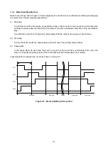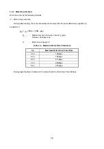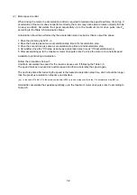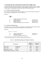
3.5.3 Adjustment of Thermal Head Resistance
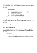
The adjusted resistance "R" can be calculated using equation (5) to adjust the thermal head resistance as a
voltage drop is caused by wiring resistance.
Equation (5):
H
SA
c
C
i
H
R
)
N
×
)
r
+
(R
+
R
+
(R
=
R
2
1.152
V
1.121
V
R
H
:
Thermal head heat element resistance
180 (
Ω
)
R
i
:
Wiring resistance in the thermal head
9 (
Ω
)
R
C
:
Common terminal wiring resistance
in the thermal head
0.438 (
Ω
)
r
C
:
Wiring resistance between V
p
and GND (
Ω
)
*1
N
SA
:
The number of simultaneously activated dots
*1: The resistance is a serial resistance of the wire and switching circuit of relay between control terminal and power supply.
3.5.4 Adjustment of Thermal Head Drive Voltage
The adjusted voltage "V" can be calculated using equation (6) as the printing density changes by the
difference of the thermal head drive voltage.
Equation (6):
p
V
P
:
Thermal head drive voltage (V)
3.5.5 Setting of Activation Pause Time
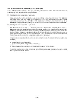
In order to protect the thermal head heat elements, when the same heat element dots are activated
continuously on the successive dot line, determine the activation pulse cycle (the time from the start of the
preceding activation to the start of the current activation) which meets equation (7) to secure the pause time.
Equation (7):
μ
s
500
+
t
W
W
:
The activation cycle (
μ
s)
*1
*1: The activation cycle W is the driving time of the printer drive motor for 2 steps (one-half
dot
line).
3-21

