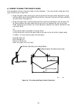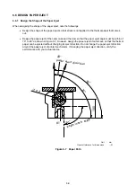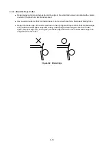
6.3 CONNECT THE PRINTER TO FRAME GROUND (FG)
To prevent the thermal head from being damaged by static electricity, it is recommended that the printer
mechanism is connected to frame ground (FG).
6.3.1 How to Connect the Printer to Frame Ground (FG)
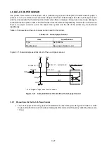
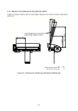
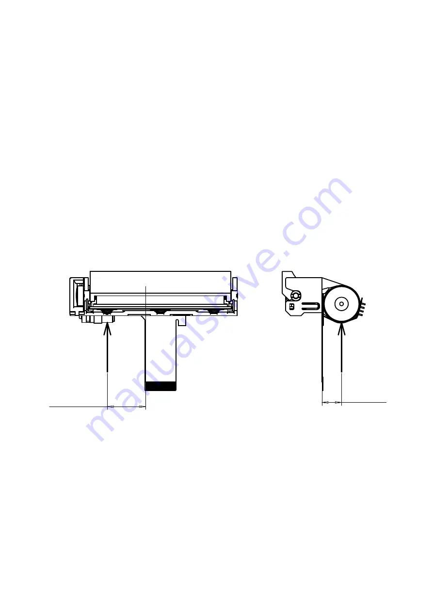
Contact the connecting parts to the area indicated by the arrows as shown in Figure 6-4.
Design the connecting parts with tension like coil spring or plate spring to reduce the contact
resistance.
The connecting force must be for arrow direction as shown in Figure 6-4, vertical to the side surface
of the printer main body.
The material of the connecting parts should have superior electrical conductivity like beryllium
copper.
The connecting force should be 1N or lower.
All Frame Ground (FG) must be same electrical potentials.
Connect the signal ground (GND) to the frame ground (FG) using a 1M
Ω
resistor so that the electric
potential of the signal ground (GND) of the thermal head and that of the frame ground (FG) of the
printer are equal.
#1
7.9 ±0.5
15.35 ±1
Unit
:
mm
Figure 6-4 Frame Ground (FG) Connecting Area
6-6

