background image

6.6.2  Mount the Paper Cutter 

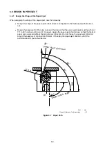
  Design paper cutter mounting position so the edge of the cutter blade does not contact with a platen 

unit when the platen unit is set and released. 

  Use a well-cut cutter so that the thermal paper can be cut with less force than paper holding force. 

  Design the blade edge of the cutter as shown in the right figure of Figure 6-8 so that the blade edge 

can guide the thermal paper edge after cutting. If designing the blade edge as shown in the left 
figure, the paper edge may be caught by the blade edge and result in the thermal paper edge to be 
caught inside of the cutter. 


Figure 6-8    Blade Edge 

6-10


Summary of Contents for LTP02-245-01

Page 1: ...LTP02 245 01 THERMAL PRINTER MECHANISM TECHNICAL REFERENCE U00128436600 ...

Page 2: ...rs The information contained herein is the property of SII and shall not be reproduced in whole or in part without the prior written approval of SII SII reserves the right to make changes without notice to the specifications and materials contained herein and shall not be responsible for any damages including consequential caused by reliance on the materials presented including but not limited to ...

Page 3: ...d in this technical reference Fully investigate the intellectual property rights of these circuits before using The printer complies with EU RoHS Directive 2002 95 EC The printer contains Pb the details are described below Printer mechanism a particular copper alloy parts a particular free cutting steel parts a particular component in glass of the electronic parts Lead containing items listed abov...

Page 4: ...Position of the Data 3 16 3 4 3 Electrical Characteristics of Thermal Head 3 17 3 4 4 Timing Chart 3 18 3 4 5 Thermal Head Heat Element Resistance 3 18 3 4 6 Maximum Current Consumption 3 19 3 5 CONTROLLING THE ACTIVATION PULSE WIDTH FOR THERMAL HEAD 3 20 3 5 1 Calculation of Activation Pulse Width 3 20 3 5 2 Calculation of Printing Energy 3 20 3 5 3 Adjustment of Thermal Head Resistance 3 21 3 5 ...

Page 5: ... 6 3 6 2 1 Recommended Shape of the Platen Holder 6 3 6 2 2 Dimensions for Positioning and Fixing the Platen Holder 6 4 6 2 3 Precautions for Fixing the Platen Holder 6 5 6 3 CONNECT THE PRINTER TO FRAME GROUND FG 6 6 6 3 1 How to Connect the Printer to Frame Ground FG 6 6 6 4 LAYOUT OF THE PRINTER MECHANISM AND THERMAL PAPER 6 7 6 5 WHERE TO MOUNT THE PAPER HOLDER 6 8 6 6 DESIGN PAPER EJECT 6 9 6...

Page 6: ...C 3 12 Table 3 8 Drive Time and Paper Length at Temperature Rise 75 C 3 13 Table 3 9 DST Terminals and Heating Elements 3 15 Table 3 10 Electrical Characteristics of Thermal Head 3 17 Table 3 11 Thermal Head Heat Element Resistance 3 18 Table 3 12 Standard Printing Energy and Temperature Coefficient 3 20 Table 3 13 Activation Pulse Width 3 23 Table 3 14 Temperature Characteristics of the Thermisto...

Page 7: ...3 24 Figure 3 11 Sample External Circuit of the Out of paper Sensor 3 27 Figure 4 1 Connecting Terminals 4 1 Figure 5 1 Divided Print Timing Chart Sample 5 1 Figure 6 1 Dimensions for Positioning and Fixing the Printer Main Body 6 1 Figure 6 2 Dimensions for Positioning and Fixing the Platen Unit 6 3 Figure 6 3 Dimensions for Positioning and Fixing the Platen Holder 6 4 Figure 6 4 Frame Ground FG ...

Page 8: ...reference can work properly and safe You shall evaluate and confirm sufficiently that such products can work properly and safe and shall be liable for any and all claims actions lawsuits demands costs liabilities losses damages and or expenses arising out of or in relating to such products SII has not investigated the intellectual property rights of the sample circuits included in this technical r...

Page 9: ...he thermal head to cool before cleaning In order to allow cooling secure clearance between the thermal head and the outer case when designing the outer case Precautions for rising temperatures of the motor Temperature of the motor and its peripherals rises very high during and immediately after printing Be sure to design the outer case to prevent users from burn injuries by touching them Place war...

Page 10: ... Connect the Signal Ground GND to the Frame Ground FG through approximately 1 MΩ resistance Always detect the outputs of the platen position sensor and out of paper sensor Never activate the thermal head when there is no thermal paper Incorrect activation of the thermal head may reduce the life of the thermal head and the platen and may damage them A pause time between thermal head activations of ...

Page 11: ...ctual device If the printer main body and the platen unit are not placed in proper position the print defect and the paper jam may occur Therefore pay special attention to it when designing the outer case For the position relation between the printer main body and the platen unit see CHAPTER 6 OUTER CASE DESIGN GUIDE Design the platen holder and the outer case strong enough to keep the allowable d...

Page 12: ...e platen unit during printing The print defect may occur When setting the platen unit the reduction gear may interfere with the platen gear and may cause the platen unit to not be set In such a case release the platen unit and set it again Never pull out the thermal paper while the platen unit is set The printer mechanism may become damaged When handling the printer make sure to use antistatic clo...

Page 13: ... The printer is not dust proof Never use the printer in a dusty place as it may damage the thermal head and paper drive system Do not use the printer in corrosive gas and siloxane atmosphere as it may cause the contact failure 1 2 3 Precautions on Discarding When discarding used printers discard them according to the disposal regulations and rules of each respective district ...

Page 14: ...es High resolution printing A high density print head of 8 dots mm produces clear and precise printing Compact Dimensions W67 3mm D18 1mm H30 0mm Mass approx 28 g High print speed Maximum 90mm s print is available Easy operation Platen unit open mechanism provides easy paper installation Maintenance Free No cleaning and no maintenance required Low noise Thermal printing technology realizes low noi...

Page 15: ...ctivated dots 45 dots Resolution W 8 dots mm H 16 dots mm 1 Paper feed pitch 0 03125 mm Maximum print speed 90 mm s 2 Print width 48 mm Paper width mm 58 0 1 Thermal head temperature detection Thermistor Platen position detection None Out of paper detection Reflection type photo interrupter Operating voltage range VP line Vdd line 5 5 V to 8 0 V 3 0 V to 3 6 V Current consumption line Thermal head...

Page 16: ...49 N 50 gf or more Paper hold force 0 78 N 80 gf or more Dimensions excluding convex part W 67 3 mm D 18 1 mm H 30 0 mm Mass Approx 28g Specified thermal paper Nippon Paper Jujo Thermal Mitsubishi Hi Tech Paper Papierfabrik August Koehler AG TF50KS E2D AF50KS E F5041 KT55F20 1 See CHAPTER 5 PRINT DRIVE METHOD for printing drive method 2 Print speed changes according to the processing speed of the ...

Page 17: ...FIGURATION Figure 3 1 shows print dot pitch Figure 3 2 shows print area 0 0625mm 0 125mm 0 125mm 48mm 384dot Figure 3 1 Print Dot Pitch 58 1 mm Paper Width 0 5 mm 48 mm Printing Width 5 mm Figure 3 2 Print Area 3 3 ...

Page 18: ...able 3 2 General Specifications of the Step Motor Item Specifications Type PM type step motor Drive method Bipolar chopper drive Excitation 1 2 phase Winding resistance per phase 8 3 Ω phase 10 Motor drive voltage VP 5 5 V to 8 0 V Motor controlled current 300 mA phase Drive pulse rate 2933 pps max 3 4 ...

Page 19: ...NC VREF REG5 REG1 IN1A OUT1A IN1B OUT1B IN2A OUT2A IN2B OUT2B ATT2 ATT1 RNF1 RNF2 CHOP GND PGND 16 22 10μF 35V Vp 13 20 18 23 14 24 6 1 Vdd 1 19 9 10 21 220pF 8 A B A B 0 1μF 12 15 1 33Ω 1 0 1μF 4 5 11 2 3 17 1 33Ω 1 1 33Ω 1 1 33Ω 1 MCL Recommended motor driver LV8711T SANYO Figure 3 3 Sample Drive Circuit ...

Page 20: ...step 4 step 5 step 6 step7 step 8 step 1 step 2 as shown in Table 3 3 START STEP 1st STEP 2nd STEP 3rd STEP 4th STEP 5th STEP 6th STEP 7th STEP 8th STEP PH1 H L PH2 H L PH3 H L PH4 H L 1 dotline 1 Set MCL to High while the motor is driven Figure 3 4 Input Voltage Waveforms for the Sample Drive Circuit Table 3 3 Excitation Sequence Input Signal Output Signal PH1 PH2 PH3 PH4 A A B B Step1 H L L L H ...

Page 21: ...e acceleration step To restart the motor from the stop step immediately shift the motor to the sequence of print step 2 Stop step To stop the motor excite the same phase as the last one in the printing step for 65ms 3 Pause state In the pause state do not excite the motor to prevent to the motor from overheating Even when the motor is not excited holding torque of the motor prevents the thermal pa...

Page 22: ...ined by equation 1 Equation 1 3 8 1339 534 V P P M pps PM Maximum motor drive pulse rate at VP pps However 2933pps max VP Motor drive voltage V Table 3 4 Maximum Motor Drive Pulse Rate Vp Maximum Motor Drive Pulse Rate 5 5 V 1598pps 6 0 V 1865pps 6 5 V 2132pps 7 5 V 2666pps 8 0 V 2933pps During paper feeding in backward the motor should be driven lower than 960pps ...

Page 23: ... at 2nd acceleration step 4 Hereinafter drive the n th step as same as acceleration step time at n th acceleration step 5 After accelerating up to the maximum motor drive pulse rate PM drive the motor at a constant speed Available to print during acceleration Follow the procedures below if Unable to accelerate the speed for the reasons above even if following the Table 3 5 The speed has been reduc...

Page 24: ...1 390 14 1178 849 63 2582 387 15 1222 818 64 2603 384 16 1265 790 65 2624 381 17 1307 765 66 2644 378 18 1347 742 67 2665 375 19 1386 721 68 2685 372 20 1424 702 69 2705 370 21 1462 684 70 2725 367 22 1498 668 71 2745 364 23 1533 652 72 2764 362 24 1568 638 73 2784 359 25 1602 624 74 2803 357 26 1635 612 75 2822 354 27 1668 600 76 2842 352 28 1700 588 77 2860 350 29 1731 578 78 2879 347 30 1762 56...

Page 25: ...uter case 100 C or lower Verify the performance with your actual device Table 3 6 Maximum Continuous Drive Time and Drive Ratio Motor Drive Voltage Vp V 8 0 7 5 6 5 5 5 Drive Pulse Rate pps Maximum Continuous Drive Time sec Drive Ratio Drive Ratio Drive Ratio Drive Ratio 320 to 480 100 45 50 55 60 480 to 640 67 45 50 55 60 640 to 800 50 45 50 55 60 800 to 960 40 45 50 55 60 960 to 1120 33 45 50 55...

Page 26: ...4 9 7 3 5 3 8 0 960 to 1120 5 1 9 1 5 1 9 2 4 9 8 9 5 4 9 8 1120 to 1280 5 0 10 5 5 1 10 8 5 0 10 5 5 6 11 7 1280 to 1440 5 0 12 0 5 1 12 3 5 1 12 1 5 7 13 7 1440 to 1600 4 9 13 3 5 1 13 9 5 1 13 8 5 8 15 7 1600 to 1760 4 9 14 7 5 1 15 4 5 2 15 5 1760 to 1920 4 9 16 0 5 2 17 0 5 2 17 2 1920 to 2080 4 8 17 4 5 2 18 6 5 3 18 9 2080 to 2240 4 8 18 6 5 2 20 1 5 3 20 7 2240 to 2400 4 7 19 9 5 2 21 7 24...

Page 27: ... 1 21 2 960 to 1120 12 8 23 1 13 2 23 8 12 2 22 0 15 5 28 0 1120 to 1280 12 8 26 9 13 5 28 4 13 0 27 2 16 9 35 6 1280 to 1440 12 8 30 7 13 8 33 2 13 7 32 9 18 4 44 0 1440 to 1600 12 8 34 5 14 1 38 1 14 4 39 0 19 8 53 3 1600 to 1760 12 8 38 3 14 4 43 2 15 2 45 6 1760 to 1920 12 8 42 1 14 7 48 4 15 9 52 6 1920 to 2080 12 7 45 9 15 0 53 8 16 7 60 0 2080 to 2240 12 7 49 6 15 2 59 4 17 4 67 9 2240 to 2...

Page 28: ...he two step times of the motor See CHAPTER 5 PRINT DRIVE METHOD for details Do not perform continuous printing to prevent the motor from overheating Surface of the thermal paper may get scratched by backward feed The backward feed may cause paper skew and jams depending on the paper roll layout and designing of the paper holder Be sure to confirm performance with your product before using the back...

Page 29: ... accordance with the stored print data Simultaneously activated dots is 45 dots 3 4 1 Structure of the Thermal Head Figure 3 6 shows the thermal head block diagram when driving the printer Table 3 9 shows the relationship between DST terminals and activated heating elements Vp DI CLK LAT TH GND Vdd DOT 1 DOT 384 DST DOT 64 DOT 65 DOT 128 DOT 129 DOT 192 DOT 193 DOT 256 DOT 257 DOT 320 DOT 321 Heat...

Page 30: ...through DI terminals are printed when driving the printer as shown in Figure 3 7 Data in Paper feed direction Paper Print surface Data 1 2 3 4 5 6 382 383 384 Printer mechanism Data input sequence 1 2 3 4 5 6 382 383 384 Figure 3 7 Transfer Data and Print Position 3 16 ...

Page 31: ...igh IIH DST Vdd 3 3V VIH Vdd 1 8 A DST input current High active Low IIL DST Vdd 3 3V VIL 0V 120 A High IIH CLK Vdd 3 3V VIH Vdd 1 0 A CLK input current Low IIL CLK Vdd 3 3V VIL 0V 1 0 A High IIH LAT Vdd 3 3V VIH Vdd 1 0 A LAT input current Low IIL LAT Vdd 3 3V VIL 0V 1 0 A CLK frequency fCLK 3 0V Vdd 3 6V 8 0 MHz CLK pulse width t1 Vdd 3 3V See the timing chart 47 5 ns DI setup time t2 Vdd 3 3V S...

Page 32: ...t5 t8 t7 CLK DI LAT DST Figure 3 8 Thermal Head Drive Timing Chart 3 4 5 Thermal Head Heat Element Resistance Table 3 11 shows resistance of the thermal head heat element of the printer Table 3 11 Thermal Head Heat Element Resistance Thermal Head Heat Element Resistance 162 0 Ω to 198 0 Ω 3 18 ...

Page 33: ...ly activated dots should be determined not to exceed power supply capacity Also allowable current for the cable material and the voltage drop on the cable should be cared well Equation 2 min H P SA P R V N I IP Maximum current consumption A NSA Number of simultaneously activated dots VP Thermal head drive voltage V RH min Minimum thermal head heat element resistance 162 0 Ω 3 19 ...

Page 34: ... section 3 5 4 C Thermal head activation pulse cycle coefficient See section 3 5 6 3 5 2 Calculation of Printing Energy The printing energy E can be calculated using equation 4 as the appropriate printing energy is different depending on each specified thermal paper and the temperature of the thermal head Equation 4 25 T T E E X C 25 E25 Standard printing energy mJ See Table 3 12 TC Temperature co...

Page 35: ...tween control terminal and power supply 3 5 4 Adjustment of Thermal Head Drive Voltage The adjusted voltage V can be calculated using equation 6 as the printing density changes by the difference of the thermal head drive voltage Equation 6 p VP Thermal head drive voltage V 3 5 5 Setting of Activation Pause Time In order to protect the thermal head heat elements when the same heat element dots are ...

Page 36: ...lf dot line 2 at step 3 and 4 W 1 shown in the figure below should be set as W defined at Equation 8 To calculate the activation pulse width t2 for the half dot line 5 at step 9 and 10 W 2 shown in the figure below should be set as W defined at Equation 8 1st step 2nd step 3rd step 4th step 5th step 6th step 7th step 8th step 9th step 10th step 1st half dot line 2nd half dot line 3rd half dot line...

Page 37: ...0 388 0 0 717 0 591 0 511 0 455 0 414 0 382 0 357 10 0 655 0 540 0 467 0 416 0 378 0 349 0 326 20 0 594 0 489 0 423 0 377 0 342 0 316 0 296 30 0 532 0 439 0 379 0 337 0 307 0 283 0 265 40 0 470 0 388 0 335 0 298 0 271 0 250 0 234 50 0 408 0 337 0 291 0 259 0 235 0 217 0 203 60 0 346 0 286 0 247 0 220 0 200 0 185 0 173 7 5 70 0 284 0 235 0 203 0 180 0 164 0 152 0 142 10 0 681 0 564 0 489 0 436 0 39...

Page 38: ... 3 11 and Table 3 14 Equation 9 298 1 T 273 1 B EXP R R X 25 X RX Resistance at TX C Ω R25 Resistance at 25 C 30kΩ 5 B B value 3950K 3 TX Temperature detected by thermistor C EXP A The A th power of natural logarithm e 2 71828 1 10 100 1000 20 15 10 5 0 5 10 15 20 25 30 35 40 45 50 55 60 65 70 75 80 85 90 95 100 温度 サーミスタ抵抗値 kΩ Resistance kΩ Tem perature Figure 3 10 Temperature Characteristics of t...

Page 39: ...he Thermistor Temperature C Thermistor Resistance kΩ 10 175 07 5 132 29 0 100 99 5 77 85 10 60 57 15 47 53 20 37 61 25 30 00 30 24 11 35 19 51 40 15 89 45 13 03 50 10 75 55 8 92 60 7 45 65 6 25 70 5 27 75 4 47 80 3 80 85 3 25 90 2 79 95 2 41 100 2 09 ...

Page 40: ...activated by malfunction of the control unit CPU the software for detecting abnormal temperatures may not function properly resulting in overheating of the thermal head Overheating of the thermal head not only may damage the thermal head but also may cause smoke fire and burn injuries Always use hardware together with software for detecting abnormal temperatures to ensure personal safety If the co...

Page 41: ...f the printer may be shortened significantly Table 3 15 shows about the out of paper sensor used for this printer Table 3 15 Out of paper Sensor Item Specification Type NJL5902R 2 Manufacturer New Japan Radio Co Ltd 3 27 Figure 3 11 shows sample external circuit of the out of paper sensor The PS signal is High when there is no paper Figure 3 11 Sample External Circuit of the Out of paper Sensor 3 ...

Page 42: ...rmly to the external circuits Table 4 1 Recommended Connectors Number of Terminals Recommended Connectors 24 MOLEX INC 0545502471 Right angle type Top contact Gold plated 4 2 CONNECTING TERMINALS Figure 4 1 shows the terminal configuration of the connecting terminals and Table 4 2 shows terminal assignments of the connecting terminals 1 24 Figure 4 1 Connecting Terminals 4 1 ...

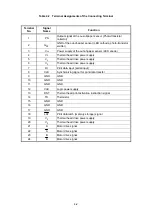
Page 43: ...hermal head drive power supply 6 VP Thermal head drive power supply 7 DI Print data input serial input 8 CLK Synchronizing signal for print data transfer 9 GND GND 10 GND GND 11 GND GND 12 Vdd Logic power supply 13 DST Thermal head print activation instruction signal 14 TH Thermistor 15 GND GND 16 GND GND 17 GND GND 18 LAT Print data latch memory storage signal 19 VP Thermal head drive power suppl...

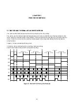
Page 44: ...our steps In order to print one dot line feed the thermal paper for four steps and activate the thermal head in every two step Figure 5 1 shows a divided print timing chart 1st dot line shows a timing chart for using three divisions printing 2nd dot line shows a timing chart for using batch printing 4th step 3rd step 2nd step 1st step Start Pause PH1 PH2 PH3 PH4 CLK DI LAT DST 1st half dot line 2n...

Page 45: ...e motor drive signal It is not necessary to synchronize the activation of the thermal head After printing the 1st half dot line at the 1st dot line the 3rd step of the motor drive signal start activation of the thermal head by synchronized the DST signal and printing the 2nd half dot line at the 1st dot line by DST After 3rd step of the motor drive signal is completed input the 4th step of the mot...

Page 46: ...ber of the activating dots for every 1 dot line printing Logical blocks are predetermined for every 1 dot line printing The maximum current consumption can be controlled within a constant value The thermal head in the printer can be driven with one DST signal The number of the simultaneously activated dots should be 45 dots or less as the physical block 5 3 ...

Page 47: ...me between thermal head activations of the same heat element shall be secured more than 0 5ms The number of the maximum thermal head division in a half dot line should be 9 or lower to maintain print quality The number of the simultaneously activated dots should be 45 dots or less ...

Page 48: ... 2 must be used for positioning the printer main body Design bosses on the outer case to position the printer main body for the positioning holes 1 and 2 The height of the bosses on the outer case must be 1 5mm max Screw up holes A and B O 2 2 O 2 1 0 0 5 27 6 2 1 0 05 33 O 2 2 O 2 9 1 A B 2 Unit mm General tolerance 0 1 Figure 6 1 Dimensions for Positioning and Fixing the Printer Main Body 6 1 ...

Page 49: ...ng paper jamming and noise during printing may be occur The printer main body to be mounted on a flat surface and prevent from vibration Connect the Frame Ground FG to Signal Ground GND through approximately 1 MΩ resistance and make the same electric potential See 6 3 CONNECT THE PRINTER TO FRAME GROUND FG for details about how to connect the Frame Ground FG Pay attention not to damage on the FPC ...

Page 50: ... recommended shape of the platen holder Platen unit 56 65 0 0 2 A Detail A R 1 O 3 1 2 5 3 2 0 1 0 R 1 3 5 O 6 8 R 1 6 1 1 4 3 1 Center of platen at setting position 1 8 53 05 1 8 3 5 3 5 1 2 8 0 0 1 Platen holder Unit mm General tolerance for dimensions 0 1 General tolerance for angles 1º Figure 6 2 Dimensions for Positioning and Fixing the Platen Unit 6 3 ...

Page 51: ...en holder which is critical for setting or releasing the platen unit 1 5 5 10 28 MIN 150 MAX The shaded area is the position of platen holder rotation center 22 325 0 2 Unit mm General tolerance for dimensions 0 1 General tolerance for angles 1º Figure 6 3 Dimensions for Positioning and Fixing the Platen Holder 6 4 ...

Page 52: ...rotation center axis of platen holder should be 0 2 or less Design the platen holder to be strong enough to stand against stress applied during releasing and setting the platen unit Prevent from excessive stress deformation and torsion when fixing the platen unit When the platen holder rotation fulcrum of the platen holder and mounting position of the platen unit are not proper engagement of the p...

Page 53: ...act resistance The connecting force must be for arrow direction as shown in Figure 6 4 vertical to the side surface of the printer main body The material of the connecting parts should have superior electrical conductivity like beryllium copper The connecting force should be 1N or lower All Frame Ground FG must be same electrical potentials Connect the signal ground GND to the frame ground FG usin...

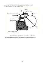
Page 54: ...5 Thermal head Thermal head heat element Paper Roll Printer mechanism Printer mounting plate Platen Out of paper sensor Platen holder Figure 6 5 Recommended Layout between the Printer and the Paper The thermal paper feeding distance between the out of paper sensor and the heat element is approximately 5 0mm 6 7 ...

Page 55: ...the printing problem and paper feed problem may occur in the following case even if it is below 0 49N Design the paper holder so as not to make these conditions and verify the performance with your actual device ex In case that the paper roll wobbles in the paper holder In case that tension of the thermal paper between the paper roll and the printer changes rapidly In addition do not use following...

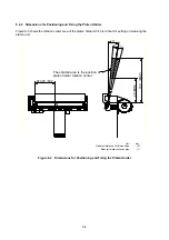
Page 56: ...paper eject angle must be within of 70 to 90 as shown in Figure 6 7 However design the paper eject of outer case so that the thermal paper can be ejected without changing its eject direction Do not change the paper eject direction around the paper eject of printer mechanism If changing the paper eject direction verify the performance with your actual device 1 20 paper eject direction 7 0 90 paper ...

Page 57: ...ermal paper can be cut with less force than paper holding force Design the blade edge of the cutter as shown in the right figure of Figure 6 8 so that the blade edge can guide the thermal paper edge after cutting If designing the blade edge as shown in the left figure the paper edge may be caught by the blade edge and result in the thermal paper edge to be caught inside of the cutter Figure 6 8 Bl...

Page 58: ...ture of the thermal head and its peripherals rises very high during and immediately after printing Be sure to design the outer case to prevent users from burn injuries by touching them Place warning labels to warn users to ensure safe operation As for thermal head cleaning warn users to allow the thermal head to cool before cleaning In order to allow cooling secure clearance between the thermal he...

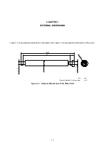
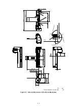
Page 59: ...hows external dimensions of the platen unit Figure 7 2 shows external dimensions of the printer 57 64 55 5 6 8 O 3 1 0 0 1 O 3 1 0 0 1 O O 8 0 5 Unit mm General tolerance for dimensions 0 5 Figure 7 1 External Dimensions of the Platen Unit 7 1 ...

Page 60: ...2 33 0 1 27 0 1 6 0 1 2 1 0 05 36 9 67 3 1 5 A A Section A A 9 0 P a p e r I n l e t A n g l e 6 6 Paper Inlet Position 9 0 P a p e r e j e c t d ir e c t io n O 6 8 12 5 10 65 2 35 Paper Inlet Position 15 35 0 1 1 2 Unit mm General tolerance for dimensions 0 5 Figure 7 2 External Dimensions of the Printer Mechanism 7 2 ...

Page 61: ...p surface of the printer mechanism as shown in the Figure 8 1 When setting the platen unit the reduction gear may interfere with the platen gear and may cause the platen unit to not be set In such a case release the platen unit and set it again If the thermal paper is skewed feed the thermal paper until the thermal paper becomes straight or install the thermal paper again Remove the paper jam with...

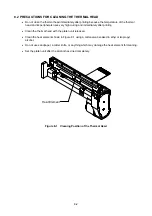
Page 62: ...mediately after printing Clean the thermal head with the platen unit released Clean the heat element shown in Figure 8 1 using a cotton swab soaked in ethyl or isopropyl alcohol Do not use sandpaper a cutter knife or anything which may damage the heat element for cleaning Set the platen unit after the alcohol has dried completely Heat Element Figure 8 1 Cleaning Position of the Thermal Head 8 2 ...

Reviews: