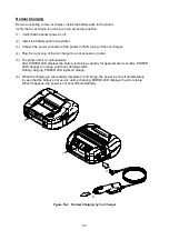
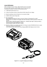


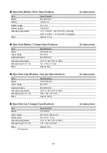

68
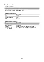
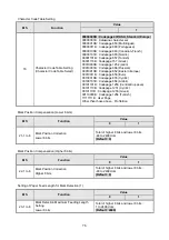
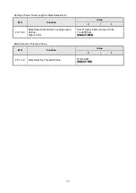
Specified Battery Pack Specifications
(Accessories)
Item
Specification
Model
BP-A0720-A1
Battery
Lithium ion
Rated voltage
DC 7.4 V
Rated capacity
1950 mAh
Operating temperature
-4°F to 122°F (-20°C to 50°C) (printing)
32°F to 104°F ( 0°C to 40°C) (charging)
Mass
Approx. 119 g
Specified Battery Charger Specifications
(Accessories)
Item
Specification
Model
PWC-A071-A1
Input voltage
DC 9.0 V
Specified battery
BP-A0720-A1
Operating temperature
32°F to 104°F (0°C to 40°C)
Dimensions (W × D × H)
54 × 123 × 41.3 mm
Mass
Approx. 82 g
Specified Quad Battery Charger Specifications
(Accessories)
Item
Specification
Model
PWC-A074-A1
Input voltage
DC 9.0 V
Specified battery
BP-A0720-A1
Operating temperature
32°F to 104°F (0°C to 40°C)
Dimensions (W × D × H)
240 × 123 × 41.3 mm
Mass
Approx. 304 g
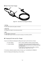
Specified Car Charger Specifications
(Accessories)
Item
Specification
Model
CC-A12-A1
Input voltage
DC 12.0 V, DC 24.0 V
Rated output
DC 12.0 V, 1.5 A
Operating temperature
32°F to 104°F (0°C to 40°C)
Dimensions (W × D × H)
107 × 38 × 20.4 mm*
Mass
Approx. 70 g
*:
Excluding cable.