


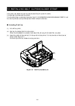


42
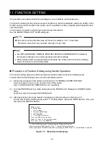
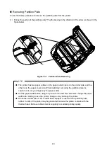
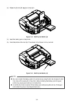
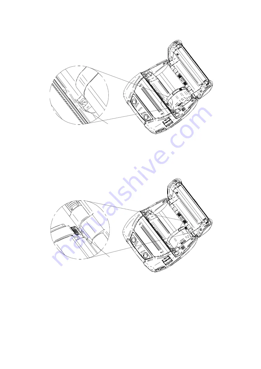
1. Align the tab of the partition plate "e" to the groove of the printer "E" as shown in the Figure
Figure 13-5 Partition Plate Installation (2)
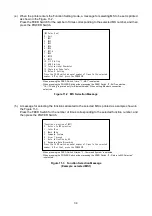
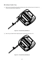
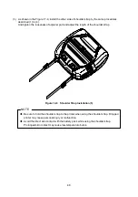
2. Rotate the partition plate clockwise with the tab "e" as a supporting point, and set the tab "f" into
the groove of the printer "F".
3. Push the tab of the partition plate "g" into the groove of the printer "G" until the partition plate
has been locked as shown in the Figure 13-6.
Figure 13-6 Partition Plate Installation (3)
(6)
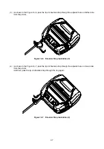
Make sure that the partition plate is installed securely into the printer.
•
See the tab "e" fixed to the groove "E"
•
See the tab "f" fixed the groove "F"
•
See the tab "g" fixed to the groove "G"
(7)
When change paper width size by the partition plate, set the General Setting 3 (MS3) in the
Function Setting to select the paper width size.
See "4.2 Details of MS Function" in "MP-A40 SERIES THERMAL PRINTER TECHNICAL
REFERENCE" for details.
e
g


