background image


5


22. GAIN: Rotary control for gain control of R, G, B, respectively respective R/G/B color channel 

that is chosen by the RGB selector 


Bottom Panel 

DIP Switch Position 

Description 

Pin#1 

Pin#2 

Pin#3 

Pin#4 

ON [

]  OFF [

]  ON [

]  OFF [

TX&RX Extender Mode –   

TxD

1

 of AV-GM03S3-S1[TX] is connected to TxD of 

AV-GM03S3-S1[RX]


RxD

2

 of AV-GM03S3-S1[TX] is connected to RxD of 

AV-GM03S3-S1[RX] 

OFF [

]  ON [

]  OFF [

]  ON [

Master to Slave Mode –     

TxD of AV-GM03S3-S1[TX] is connected to RxD of 

AV-GM03S3-S1[RX]


RxD of AV-GM03S3-S1[TX] is connected to TxD of 

AV-GM03S3-S1[RX] 


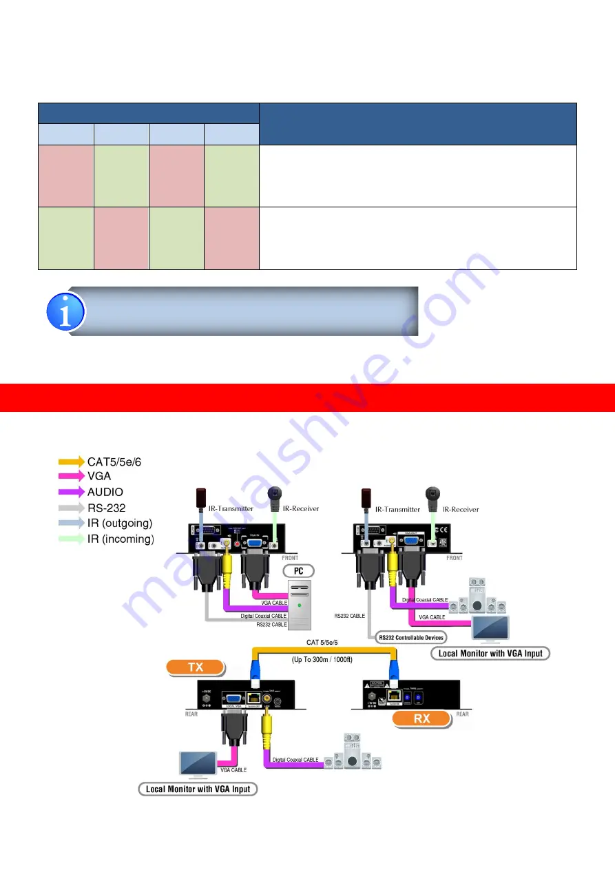
CONNECTION DIAGRAM 


1. TxD: The 3

rd

 pin of RS-232, which is in charge of sending data


2. RxD: The 2

nd

 pin of RS-232, which is in charge of receiving data


Summary of Contents for AV-GM03S3-S1

Page 1: ...VGA component Audio RS 232 over CAT5 Extender with IR Pass through P N AV GM03S3 S1...

Page 2: ...unit Do not attempt to service this unit yourself except where explained in this manual Provide proper ventilation and air circulation and do not use near water Keep objects that might damage the devi...

Page 3: ...ty and video bandwidth In order to extend the control path AV GM03S3 S1 also built RS 232 half duplex long range extender along with VGA component video signals FEATURES Supports up to WUXGA 1920x1200...

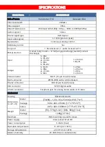
Page 4: ...VGA 2x 3 5mm 1x RCA 1x VGA 1x RS 232 1x RCA 1x 3 5mm VGA connector HD 15 15 pin D sub female RJ 45 connector WE SS 8P8C with 2 LED indicators RS 232 connector DE 9 9 pin D sub female RCA connector S...

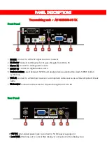
Page 5: ...to digital audio source 5 Push in button select between S PDIF and analog stereo audio button down S PDIF button up Stereo 6 VGA IN connect to a VGA input source or a component video source via a VGA...

Page 6: ...14 IR Receiver Connect to the IR receiver 15 Audio OUT Connect to analog audio output 16 S PDIF OUT Connect to digital audio output 17 VGA OUT VGA output to a VGA display or component video display vi...

Page 7: ...TxD1 of AV GM03S3 S1 TX is connected to TxD of AV GM03S3 S1 RX RxD2 of AV GM03S3 S1 TX is connected to RxD of AV GM03S3 S1 RX OFF ON OFF ON Master to Slave Mode TxD of AV GM03S3 S1 TX is connected to...

Page 8: ...n IR receiver here to receive all IR command signals from the IR remote controls of the associated devices AV GM03S3 S1 Rx IR Blaster Plug in an IR blaster here to emit all IR command signals received...

Page 9: ...A CODE RCM CODE MATSUSHITA CODE MITSUBISHI CODE ZENITH CODE JVC CODE M50560 001P MN6125H MN6125L MN6014_C5D7 MN6014 C6D6 MC14457P LC7464 AHEA GEMINI_CM You can buy any IR extension cables in the marke...

Page 10: ...smitting and receiving units 4 Make sure this Cat 5 5e 6 cable is tightly connected and not loose 5 Plug in 5V DC power supply unit to the power jack of the receiving unit AV GM03S3 S1 Rx 6 Plug in 5V...

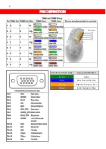
Page 11: ...9 8 PIN DEFINITION Pair of Cat 5 5e 6 Cable Associated Definition Green Audio Blue RED channel of VGA Orange GREEN channel of VGA Brown BLUE channel of VGA...

Page 12: ...ssion range than stranded STP CAT6 cable For long extension users solid UTP STP cables are the only viable choice 3 To reduce the interference among the unshielded twisted pairs of wires in UTP cable...

Page 13: ...risk of loss or damage in transit Under no circumstances will a unit be accepted without a return authorization number The warranty is in lieu of all other warranties expressed or implied including w...

Reviews: