7
HARDWARE INSTALLATION
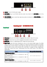
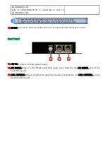
1. Connect a HDMI or DVI source (such as a Blu-ray Disc player) to the transmitting unit
AV-GM04D3-S1-TX.
2. Connect a HDMI or DVI display (such as a LCD TV) to the receiving unit AV-GM04D3-S1-RX.
3. Connect IR Blaster/Receiver to both TX and RX units.
4. Connect a Cat-5/5e/6 cable between the transmitting and receiving units.
5. Make sure this Cat-5/5e/6 cable is tightly connected and not loose.
6. Plug in 5V DC power supply unit to the power jack of the receiving unit AV-GM04D3-S1-RX.
7. Plug in 5V DC power supply unit to the power jack of the transmitting unit AV-GM04D3-S1-TX.
8. If you see flickering or blinking image on the display, please adjust the rotary control switch to
improve the cable skew. MAX stands for the strongest HDMI signal level for longest possible
transmission length while MIN stands for the weakest HDMI signal level for short transmission
length. Please adjust the signal level from MIN to MAX and stop turning the rotary switch
whenever the audio/video is playing normally. Inappropriate signal level setting may cause
overpowering issue that would shorten the product life significantly!
PIN DEFINITION
Type A (Receptacle) HDMI
Pin 1
TMDS Data2+
Pin 11 TMDS Clock Shield
Pin 2
TMDS Data2 Shield
Pin 12 TMDS Clock–
Pin 3
TMDS Data2–
Pin 13 NC
Pin 4
TMDS Data1+
Pin 14 Reserved (N.C. on device)
Pin 5
TMDS Data1 Shield
Pin 15 SCL
Pin 6
TMDS Data1–
Pin 16 SDA
Pin 7
TMDS Data0+
Pin 17 DDC/CEC Ground
Pin 8
TMDS Data0 Shield
Pin 18 +5V Power
Pin 9
TMDS Data0–
Pin 19 Hot Plug Detect
Pin 10 TMDS Clock+


