background image


6


NOTICE 

1.  While connecting a new monitor to the splitter, experiencing a short period of time no display 

may be expected. Automatic EDID learning will analyze the newly connected monitor to see if 
the EDID for the HDMI input is necessary to update! 


2.  For long range high definition HDMI transmission applications, please adopt CAT5/6 cable based 

HDMI extenders. 


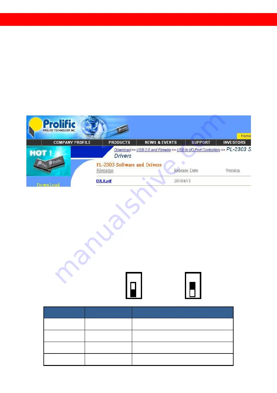
3.  Users  need  to  install  USB  driver  before  applying  firmware  update  process!  Please  search  for 

“PL2303” by Google and therefore use the most updated driver for your OS! 


4.  For  firmware  update  through  USB  and  since  there  are  2  independent  microcontrollers  in 

AV-GM06E3-S1E, users MUST follow different steps to complete the firmware update! For some 
cases, users may need to update both controllers, but in most of the cases, only one of them 
may need to be upgraded. For normal uses, please do not connect USB cable to the USB port. 
Please also disconnect all the HDMI source and displays to avoid any other possibilities to cause 
technical issues. A 2-pin DIP switch is used for firmware update, and users can access this switch 
from the bottom of the unit. The following table demonstrates the functionality that users can 
change through different pin combinations. 


Pin ON (

):                  Pin OFF (

): 

Combination # 

Pin # 1 & 2 

Functionality when USB is connected 

ON (

)ON (

MIC#1 enters updating mode 

ON (

)OFF (

MIC#1 enters updating mode 

OFF (

)ON (

MIC#2 enters updating mode 

OFF (

)OFF (

MIC#2 prepares to enter updating 

NO 

NO 

Summary of Contents for AV-GM06E3-S1E

Page 1: ...1x4 HDMI Splitter with EDID Manager ...

Page 2: ...ed on this unit Do not attempt to service this unit yourself except where explained in this manual Provide proper ventilation and air circulation and do not use near water Keep objects that might damage the device and assure that the placement of this unit is on a stable surface Use only the power adapter and power cords and connection cables designed for this unit Do not use liquid or aerosol cle...

Page 3: ... quality A V broadcasting digital signage and education applications FEATURES Support HDMI Deep Color 3D DVI 1 0 compliant HDCP 1 2 compliant Wide Frequency Range 25MHz 225MHz Video bandwidth 6 75Gbps Supports conversion of HDMI signaling to DVI Resolution up to 1080p or WUXGA 1920x1200 60 Automatic EDID learning 4 DIP switch controllable EDID sets Supports x v YCC x v Color Deep Color Supports CE...

Page 4: ...lts peak to peak TTL ESD protection 1 Human body model 19kV air gap discharge 12kV contact discharge 2 Core chipset 8kV PCB stack up 4 layer board impedance control differential 100Ω single 50Ω Input 1x HDMI Output 4x HDMI HDMI connector Type A 19 pin female Switch number 4 Mechanical Housing Metal enclosure Dimensions L x W x H Model 195 x 109 x 27mm 7 7 x 4 3 x 1 Package 330 x 200 x 95mm 1 1 x 7...

Page 5: ...tion PANEL DESCRIPTIONS Rear Panel 1 HDMI IN HDMI input source 2 HDMI OUT 1 4 distributed HDMI outputs 3 USB for firmware update use only 4 POWER Red light means power is on 5 5V DC connect to 5V 2A interlocking power supply unit Top Panel 6 SW1 8CH 2CH 7 SW2 1080P 720P 8 SW3 Present Auto ...

Page 6: ... Shield Pin 17 DDC CEC Ground Pin 5 TMDS Data1 Shield Pin 12 TMDS Clock Pin 18 5V Power Pin 6 TMDS Data1 Pin 13 NC Pin 19 Hot Plug Detect Pin 7 TMDS Data0 HARDWARE INSTALLATION Broadcasts HDMI signal to 4 HDMI displays 1 Switch off all devices including monitors 2 Connect to the receivers 3 Connect an HDMI source such as a Blu ray Disc player to the HDMI In 4 Plug in 5V DC power supply unit 5 Powe...

Page 7: ...5 CONNECTION DIAGRAM ...

Page 8: ...6E3 S1E users MUST follow different steps to complete the firmware update For some cases users may need to update both controllers but in most of the cases only one of them may need to be upgraded For normal uses please do not connect USB cable to the USB port Please also disconnect all the HDMI source and displays to avoid any other possibilities to cause technical issues A 2 pin DIP switch is us...

Page 9: ...ogram With Verification selected and then click on START button on the bottom of the window Wait for seconds until the update process is completed After firmware update is successfully accomplished please unplug USB cable and power off the splitter 6 For updating the second microcontroller if necessary please execute the attached firmware program as below first After the Firmware Writer is execute...

Page 10: ...n transit Under no circumstances will a unit be accepted without a return authorization number The warranty is in lieu of all other warranties expressed or implied including without limitations any other implied warranty or fitness or merchantability for any particular purpose all of which are expressly disclaimed Proof of sale may be required in order to claim warranty Customers outside Taiwan ar...

Reviews: