background image

3

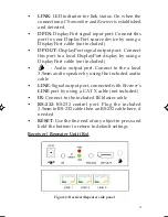
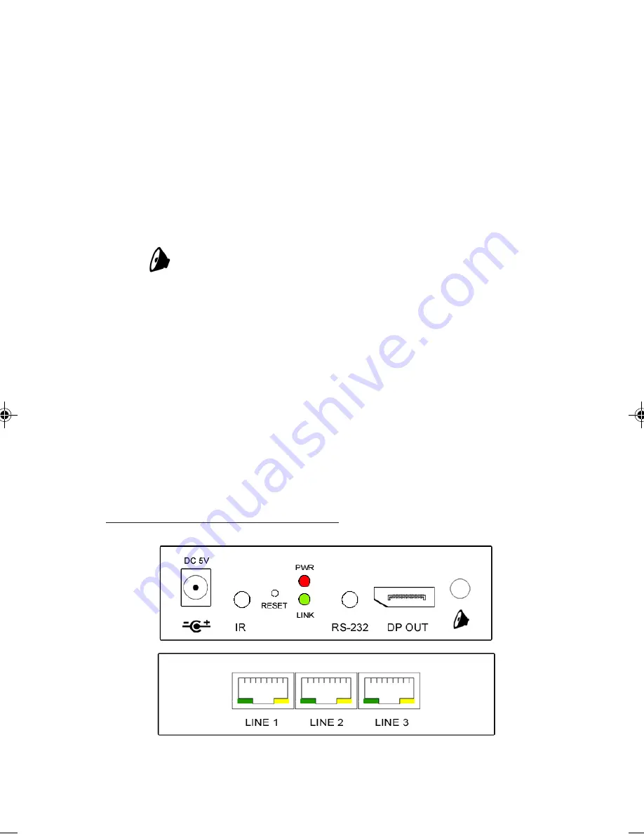
LINK

: LED indicator for link status. On when the

connection of 

Transmitter

 and 

Receiver

 is established

and detected

DP IN

: DisplayPort signal input port. Connect this

port to your DisplayPort source device by using a

DisplayPort cable (not included)

DP OUT

: DisplayPort signal output port.  Connect

this port to a local DisplayPort display by using a

DisplayPort cable (not included)

        : Audio output port. Connect to the a local

3.5mm audio speaker by using the included audio

cable

LINE 

: Signal output port, connected with 

Receiver

's

LINE 

port by using a CAT X cable (not included)

IR

: Connect to the included IR blaster cable

RS-232

: RS-232 control port. Plug the included

3.5mm to RS-232 cable then an RS-232 cable here, if

needed

RESET

: Use the fine end of any object to press and

hold the bottom to return to default settings

Receiver / Repeater Unit (Rx)

Figure 2: Receiver/Repeater side panel

Summary of Contents for CE-DP0511-S1

Page 1: ...turesandBenefits Extend DisplayPort signals up to 100m over Cat5e 6 cabling Cascade receivers up to 10 layers Supports video high resolution Full HD 1080p 1920 x 1080 60Hz Supports local DisplayPort a...

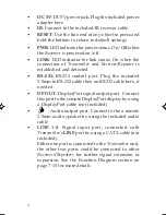
Page 2: ...out Transmitter Unit Tx Figure 1 Transmitter side panel DC 5V DC 5V power jack Plug the included power adapter here PWR LEDindicatorforpowerstatus On Offwhen the Transmitter is powered on off CE DP061...

Page 3: ...using a DisplayPort cable not included Audio output port Connect to the a local 3 5mm audio speaker by using the included audio cable LINE Signal output port connected with Receiver s LINE port by usi...

Page 4: ...g the included 3 5mm to RS 232 cable then an RS 232 cable here if needed DP OUT DisplayPort signal output port Connect this port to the remote DisplayPort display by using a DisplayPort cable not incl...

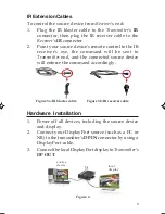
Page 5: ...e command will be sent to Transmitter end and the connected source device will enforce the command accordingly Figure 3a IR blaster cable Figure 3b IR receiver cable Hardware Installation 1 Power off...

Page 6: ...ports separately Skip this step if RS 232 controlling is not needed 7 Connect your CAT5 6 cable between the Transmitter s and Receiver s LINE port Make sure the CAT5 6 LAN cable is securely connected...

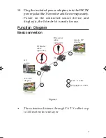
Page 7: ...rs for one layer 10 Plug the included power adapters into the DC 5V powerjackoftheTransmitterandReceiverseparately Power on the connected source device and display s the Extender kit is ready for use...

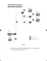
Page 8: ...layPort cable AdvancedConnections Daisy Chain Connection Figure 8 The extension distance through CAT X cable is up to 100 meters for one layer DP Display DP Display Rx DP Display DP source DP Display...

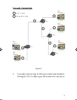
Page 9: ...P source DP Display DP Display DP Display DP Display Rx Rx Rx Tx 1 1 1 2 2 2 Figure 9 2 Cascadereceiversupto10layers extensiondistance through CAT X cable up to 100 meters for one layer 2 2 1 CAT X ca...

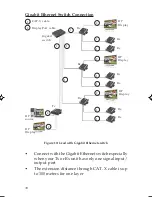
Page 10: ...x 1 1 1 1 2 2 2 2 Rx Gigabit switch DP Display Rx 2 1 1 1 1 1 Rx Rx Rx Rx Rx Rx Connect with the Gigabit Ethernet switch especially when your Tx or Rx unit has only one signal input output port The ex...

Page 11: ...t is within the store s return policy period please return the product to the store where you purchased it B If your purchase has passed the store s return policy period please follow these steps to h...

Page 12: ...n be found in many computer retail stores mail order catalogs and e commerce sites in the Americas as well as through major distributors system integrators and VARs PRODUCT NAME DisplayPort to CAT5e D...

Reviews: