background image

6

4.

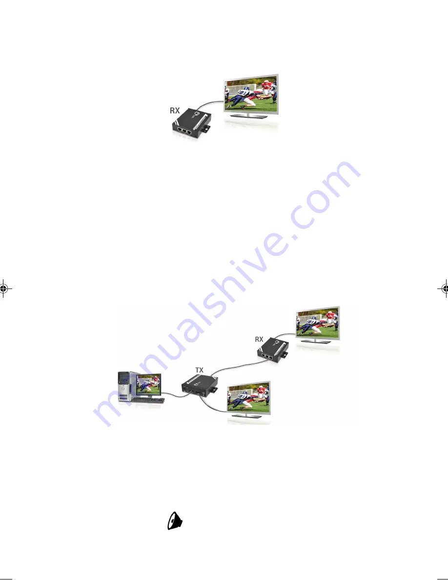
Connect remote DisplayPort display (such as a LCD

TV) to the receiver's 

DP OUT

 connector.

output

display

Figure 5

5.

Connect the

 IR blaster cable 

and 

IR receiver cable

to the

 Transmitter

 and 

Receiver

's 

IR

 ports separately.

Skip this step if not needed.

6.

Connect the two 3.5mm to RS-232 cables to the

Transmitter

 and 

Receiver

's 

RS-232

 ports separately.

Skip this step if RS-232 controlling is not needed.

7.

Connect your CAT5/6 cable between the

Transmitter

's and 

Receiver

's 

LINE

 port. Make sure

the CAT5/6 LAN cable is securely connected.

Figure 6

remote

output

display

local
output

display

source

device

8.

Each 

Receiver/Repeater

 can cascade-chainable to 2

more 

Receivers/Repeaters

 for further extending or

expanding . Skip this step if not needed.

9.

Connect the speakers to the 

Transmitter

 and 

Receiver

's

audio out

            ports separately.

Skip this step if not needed.

CAT5/

6 cable

Summary of Contents for CE-DP0511-S1

Page 1: ...turesandBenefits Extend DisplayPort signals up to 100m over Cat5e 6 cabling Cascade receivers up to 10 layers Supports video high resolution Full HD 1080p 1920 x 1080 60Hz Supports local DisplayPort a...

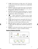
Page 2: ...out Transmitter Unit Tx Figure 1 Transmitter side panel DC 5V DC 5V power jack Plug the included power adapter here PWR LEDindicatorforpowerstatus On Offwhen the Transmitter is powered on off CE DP061...

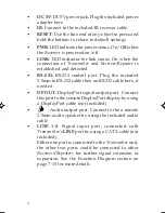
Page 3: ...using a DisplayPort cable not included Audio output port Connect to the a local 3 5mm audio speaker by using the included audio cable LINE Signal output port connected with Receiver s LINE port by usi...

Page 4: ...g the included 3 5mm to RS 232 cable then an RS 232 cable here if needed DP OUT DisplayPort signal output port Connect this port to the remote DisplayPort display by using a DisplayPort cable not incl...

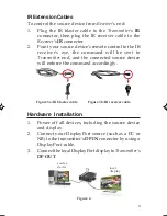
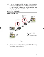
Page 5: ...e command will be sent to Transmitter end and the connected source device will enforce the command accordingly Figure 3a IR blaster cable Figure 3b IR receiver cable Hardware Installation 1 Power off...

Page 6: ...ports separately Skip this step if RS 232 controlling is not needed 7 Connect your CAT5 6 cable between the Transmitter s and Receiver s LINE port Make sure the CAT5 6 LAN cable is securely connected...

Page 7: ...rs for one layer 10 Plug the included power adapters into the DC 5V powerjackoftheTransmitterandReceiverseparately Power on the connected source device and display s the Extender kit is ready for use...

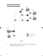
Page 8: ...layPort cable AdvancedConnections Daisy Chain Connection Figure 8 The extension distance through CAT X cable is up to 100 meters for one layer DP Display DP Display Rx DP Display DP source DP Display...

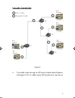
Page 9: ...P source DP Display DP Display DP Display DP Display Rx Rx Rx Tx 1 1 1 2 2 2 Figure 9 2 Cascadereceiversupto10layers extensiondistance through CAT X cable up to 100 meters for one layer 2 2 1 CAT X ca...

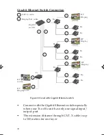
Page 10: ...x 1 1 1 1 2 2 2 2 Rx Gigabit switch DP Display Rx 2 1 1 1 1 1 Rx Rx Rx Rx Rx Rx Connect with the Gigabit Ethernet switch especially when your Tx or Rx unit has only one signal input output port The ex...

Page 11: ...t is within the store s return policy period please return the product to the store where you purchased it B If your purchase has passed the store s return policy period please follow these steps to h...

Page 12: ...n be found in many computer retail stores mail order catalogs and e commerce sites in the Americas as well as through major distributors system integrators and VARs PRODUCT NAME DisplayPort to CAT5e D...

Reviews: