background image

5

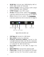
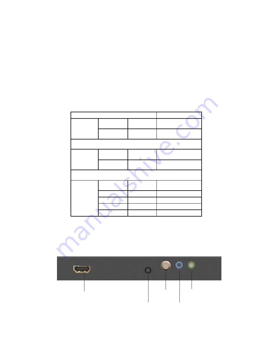
Figure 3: Receiver (RX) - front

USB Type-A: 

Connect to USB Device

Micro USB:

 Connect to USB Host

Phoenix connector (RS232): 

Connect to the

included terminal block and RS-232 connector

(not included), then connect to a serial port device

or computer for data transferring

Dip Switch: 

Refer to below table for configuration

- ON: In lower position
- OFF: In upper position

RJ45 (HDBT Out): 

Connect the Cat5e/6 cable

Power Jack: 

Connect the included 24V DC power

adapter here (or the Receiver's power jack)

HDMI Out

Stereo

Output

IR In

S/PDIF

Output

IR Out

DIP Switch Position

Description

Pin 1 (option 1)

TX

On (default)

Connect Micro USB port to
USB Host

RX

OFF (default)

Connect USB device to

Type-A port

Pin 1 (option 2)

TX

OFF

Connect USB device to

Type-A port

RX

ON

Connect Micro USB port to
USB Host

Pin 2 & 3

Pin 2 (TX & RX)

Pin 3 (TX & RX)

ON

ON

HDBaseT firmware update

ON

OFF

HDBaseT monitor mode

OFF

ON

System firmware update

OFF (default)

OFF (default)

HDMI extender mode

Summary of Contents for CE-H23211-S1

Page 1: ...1 4K HDR HDMI 2 0 USB 2 0 Extender Over HDBaseT with RS 232 IR User Reference Guide 04 1123A P N CE H23411 S1...

Page 2: ...HD for a state of the art entertainment experience PoC Power over Cable feature only one power adapterisrequiredtopowerboththetransmitter and receiver units Bi directional IR sensors allow you to remo...

Page 3: ...ctors TX 1x 19 pin HDMI Type A Female 1x 3 5mm audio jack Stereo 1x 3 5mm IR Blaster 1x 3 5mm IR Receiver 1x 9 pin USB Type A Female Device 1x Micro USB Female Host 1x Dip switch 1x 3 pin phoenix conn...

Page 4: ...here with an HDMI cable cable not included Stereo Input Provides a channel to extend an external analog audio to receiver over HDBaseT IR Out Infrared 3 5mm socket Plug IR Blaster extension cable her...

Page 5: ...the Cat5e 6 cable Power Jack Connect the included 24V DC power adapter here or the Receiver s power jack HDMI Out Stereo Output IR In S PDIF Output IR Out DIP Switch Position Description Pin 1 option...

Page 6: ...n cable here See instructions on page 8 USB Type A Micro USB RS 232 RJ45 Dip Switch Power Jack USB Type A Connect to USB Device Micro USB Connect to USB Host Phoenix connector RS232 Connect to the inc...

Page 7: ...Phoenix connector 2 Connect the wires not included to the included TerminalBlockandtheRS232connectorasbelow diagram Via pin to pin Parallel connector or cable Figure 5 TX RX GND 3 TXD 5 GND 2 RXD Fig...

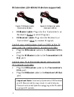
Page 8: ...to the Receiver s IR In port Plug the IR Blaster cable to the Transmitter s IR Out port Control your TV at the media player side using the TV s remote controller Plug the IR Receiver cable to the Tran...

Page 9: ...ts 5 Connect audio source to TX and audio receiver speaker to RX unit 6 Connect your HDMI display to the Receiver s HDMI OUT connector with a HDMI cable not included 7 Optional Connect the IR Receiver...

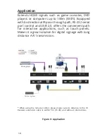
Page 10: ...SB 2 0 offers the convenient path for interactive applications such as touch panels Makes it a great solution for digital signage with long distance A V transmission Figure 9 Application When using th...

Page 11: ...A If it is within the store s return policy period please return the product to the store where you purchased it B Ifyourpurchasehaspassedthestore sreturnpolicyperiod pleasefollowthese steps to have t...

Page 12: ...e manufacturer warranty SIIG products can be found in many computer retail stores mail order catalogs and e commerce sites in the Americas as well as through major distributors system integrators VARs...

Reviews: