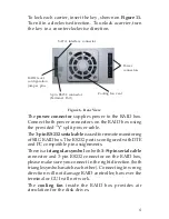
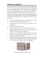
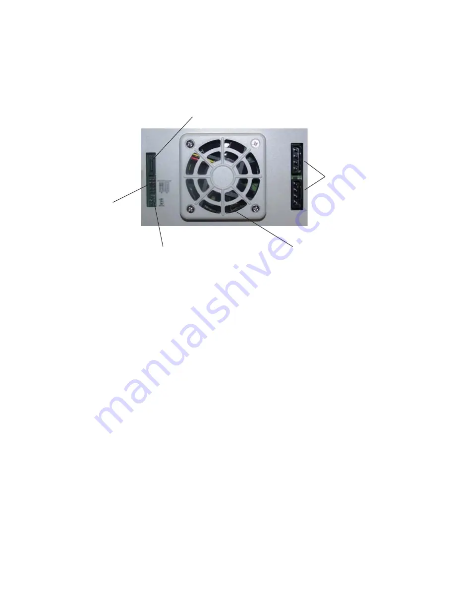
background image

5

Figure 6.  Rear View

The

 power connector

 supplies power to the RAID box.

Connect both power connectors on the RAID box using

the provided "Y" split power cable.
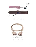
The 

3-pin RS232  serial cable 

is used for remote monitoring

of SIIG RAID box. The RS232 port is configured with DTE

and PC compatible pin assignments.
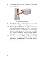
There is a 

triangular symbol 

on both 

3-/9-pin serial


cable

connector and 3-pin RS232 connector on the RAID box,

please make sure you connect in the right direction (both

triangle symbols match each other).  Connecting in wrong

direction will not damage RAID controller, however the

terminal or GUI will not work.
The 

cooling fan

 inside the RAID box provides air

circulation for the disk drives.

Cooling fan vent

Power

connectors

RAID level

configuration

jumper pins

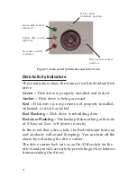
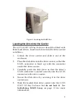
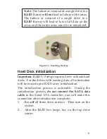
To lock each carrier, insert the key, shown on 

Figure 11.

Turn it in a clockwise direction.  To unlock a carrier, turn

the key in a counterclockwise direction.

SATA interface connector

3-pin RS232 connector

(Terminal Port)

Summary of Contents for SC-000081-S1

Page 1: ...s RAID 5 or RAID 0 Driverless needs no driver on the host side Hot swapping hard drives Automatic online data rebuilding and bad sector recovery Key lock security against unauthorized access LED indic...

Page 2: ...carriers identical Null modem 9 9 pin and 3 9 pin serial cables Y split power SATA data cables Quick Installation Guide and RAID GUI software Layout Drive carriers Figure 2 Front view Figure 1 Layout...

Page 3: ...3 Figure 3 3 9 pin serial cable 9 pin RS232 female connector Figure 4 Null Modem cable 3 pin RS232 connector 9 pin RS232 male connector...

Page 4: ...ccessed Red Disk drive is not present not properly installed unlocked or disk has failed Red Flashing Disk drive is rebuilding data Red slow Flashing The backup disk marking at the rate of 0 5sec on 2...

Page 5: ...connector on the RAID box please make sure you connect in the right direction both trianglesymbolsmatcheachother Connectinginwrong direction will not damage RAID controller however the terminal or GUI...

Page 6: ...y by placing jumpers over the ten jumper pins on the rear of the RAID box RAIDJumperSettings RAID 0 place two jumpers over the top two rows pins RAID 5 no jumpers are placed over the 5 pairs of pins 1...

Page 7: ...computer s case for a few seconds 1 Turn OFF the power to your computer and any other connected peripheral devices 2 Unplug the power cord from the back of the computer 3 Open your computer case 4 Rem...

Page 8: ...hassis from an available expansion slot Install the connector bracket with 9 pin serial port and secure it with a mounting screw Connect one end of the null modem cable to the 9 pin serial port and th...

Page 9: ...disk drive into the drive carrier so that the SATA connector is lined up with the connector inside the drive carrier 3 Carefully push the disk drive so that the drive s SATA connector is seated secure...

Page 10: ...rray RAID rebuilding will be processed automatically in the backgroundandtheRAIDboxwillrecordit sprogress If the host system is powered off or shutdown abnormally the RAID box will continue the disk r...

Page 11: ...k Initialization Important RAID 5 0 setup requires 3 new or blank hard disks For the drives with existing data all information will be erased upon RAID array initialization The initialization process...

Page 12: ...from the point of interruption when power is returned Disk Activity Indicator During Array Initialization During array initialization the following will be observed Green solid Yellow solid Red flash...

Page 13: ...e to the terms click Next 5 Type a Name and Company if desired click Next 6 Accept the default folder click Next 7 At the Shorcut folder select the option that best fits your needs then click Next 8 C...

Page 14: ...SIIGViewServericonwillappearonthetaskbar by the system clock SIIGViewServerMenuOptions Run at Windows Startup Allows SIIGView Server to startup automatically at Windows startup 1 Right click the SIIGV...

Page 15: ...e entries in the top two boxes should be identical Administrator s Email Enter the email address for one or two administrators Delay Time Minute Alert emails will continue to be sent until the problem...

Page 16: ...op up message SIIGView browser will pop up message window when event occur if this option is enable Default is enabling Controller information Lists model name serial number and RAID level of the RAID...

Page 17: ...ounterparts inside the drive carrier and try again If this does not solve the situation go to next suggestion below Change the disk drive with a new one and try again Exchange the top and bottom drive...

Page 18: ...18 Blank Page...

Page 19: ...t repaired or replaced Step 1 Submit your RMA request Go to www siig com click Support then RMA to submit a request to SIIG RMA If the product is determined to be defective anRMAnumberwillbeissued SII...

Page 20: ...ding interference that may cause undesired operation THE PARTY RESPONSIBLE FOR PRODUCT COMPLIANCE SIIG Inc 6078 Stewart Ave Fremont CA 94538 3152 About SIIG Inc Foundedin1985 SIIG Inc isaleadingcomput...

Reviews: