3
Construction and function
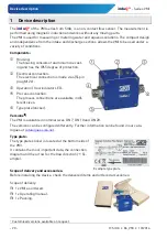
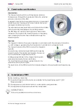
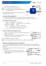
Construction:
The measuring tube with its earthing sleeves and elec-
trodes passes through the housing and forms the external
process connection of the VMI.
A magnetic field for the measurement process is generated
inside the sensor housing, which also contains the sensor
and signal conditioning circuitry.
The two stainless steel electrodes are located in the middle
of the measuring tube between the earthing sleeves.
The VMI does not need any moving parts to make meas-
urements. The inside of the measuring tube is completely
open, allowing the fluid to flow unhindered through the
measuring tube.
Function:
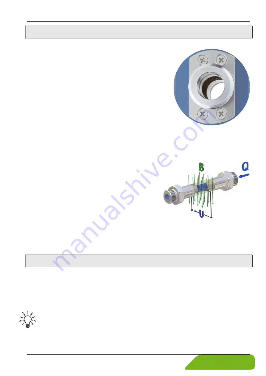
The magnetic inductive flow sensor operates in accordance with the principle of induction,
i.e. a DC voltage is generated by the movement of a conductor in a magnetic field:
The measuring tube of the VMI is located in a magnetic
field (B).
An electrically conductive liquid (Q) flows through the
measuring tube. The positive and negative charge car-
riers are deflected in opposite directions.
A voltage perpendicular to the magnet field is gener-
ated and picked up by the two electrodes.
The resulting induced voltage is proportional to the
mean flow velocity of the liquid.
The electronics of the VMI converts the induced voltage to a flow-proportional frequency sig-
nal.
4
Installation of VMI
Before installing, check that
the wetted materials of the device are suitable for the liquid being used (
the equipment is switched off and is in a safe and de-energised state.
the equipment is depressurised and has cooled down.
SUITABLE TOOLS:
Use only suitable tools of the correct size.

