Commissioning and measuring mode
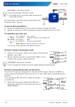
IMPORTANT! Check the frequency input of the PLC!
Please ensure that your PLC is able to process the high frequencies of the VMI output
signal.
If lower frequencies are necessary, the VMI can optionally be delivered with a custom-
specific pulse rate (
6
Commissioning and measuring mode
Before switching on the VMI for the first time, please follow the instructions in the following
section.
6.1
Commissioning
Check that
the VMI has been installed correctly and that all screw connections are sealed.
the electrical wiring has been connected properly.
the measuring system is vented by flushing.
6.2
Switching on and off
The VMI has no switch and can therefore not be switched on and off independently. Switching
on and off takes place via the connected supply voltage.
Switch on the supply voltage.
The green LED blinks 4 times. The VMI is ready for use and goes
into measuring operation.
6.3
Measuring mode
In measuring mode, the green LED flashes corresponding to the frequency of the output sig-
nal.
The human eye cannot detect the flashing any longer from a
frequency of ~30 ... 40 Hz.
In that case the green LED seems to be lit permanently.
Frequency output:
The frequency output provides a flow proportional
NPN square wave signal.
The amplitude corresponds approximately to the sup-
ply voltage.
Analogue output (optional):
The analogue output provides a flow proportional signal current of 4…20 mA.

