Electrical connection
IOB / IOM / IO3
- 14 -
© SIKA • Ba_IO • 11/2021
4 Electrical connection
DANGER
Risk of death due to electric current.
The electrical connection of the device should only be carried out by a fully
qualified electrician.
Always de-energize the system before connecting the device.
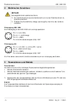
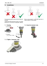
Pin assignment IOB / IOM
The pin assignment is specified according to IEC 60974-5-2 as follows:
Pin 1: L+ (24 VDC)
Pin 2: n. c. (not connected)
Pin 3: L- (GND)
Pin 4: Communication signal (C/Q) / OUT
Pin assignment IO3
Pin 1: L+ 24 VDC / 4...20 mA (Pin 1 and 2)
Pin 2: - (GND current loop)
Pin 3: L- (GND)
Pin 4: Communication signal (C/Q) / OUT
In addition to IO-Link communication, the pins are also used to supply the device.
5 Parameterisation and operation
Parametrisation
You have the following options with an IO-Link-capable parameterisation tool:
•
Read out current process values
•
Read out current parameter settings, change them, save them and transfer them to other
temperature sensors of the same type
Connect the temperature sensor to a PC or PLC with suitable parameterisation software
via the IO-Link interface.
Operation
The temperature sensor is in run mode (normal working mode) after switching on the power
supply.
2
4
3
1
2
4
3
1


