© SIKA • Ba_SolTemp_en.doc 08/2012
5 Display
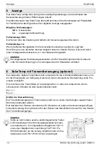
The SolarTemp has a large 4-digit digital display which allows the reading of the measuring
value from extended distances.
The microprocessor of the SolarTemp permanently checks the plausibility of the sensor sig-
nal. In the event of an error, the result is provided at the digital display:
Possible error messages:
SEn
Sensor
error
Lo
Inadequate
lighting
Error message SEn:
The sensor or the supply line are defective and have to be replaced.
Error message Lo:
If the light intensity for the solar cell is for a short-time to low, the SolarTemp does not display
a correct value until the next self-adjustment. This will be shown through display change be-
tween “Lo” and measuring value.
NOTICE
The high-quality solar cells are covered for artificial light. There can be a power loss if it
use for sunlight.
6 SolarTemp with transmitter output (optional)
The integrated, digital transmitter is supplied by the 2-wire loop voltage and provides a 4-20
mA-analogue signal. This ensures constant process monitoring.
The connection of the transmitter has reverse polarity protection to ensure that the instrument
is not damaged even if the connections are interchanged:
Pol 1 = +
Pol 2 = -
Applies to the explosive atmosphere version:
The transmitter output of the thermometer should only be operated within a certified intrinsi-
cally safe circuit.
The connector can be disconnected in explosive atmospheres due to the certified intrinsically
safe circuit. This applies to the connector of the measuring sensor and the connector of the
transmitter output.
NOTICE
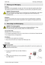
The current output transmitter of the DiTemp may be
susceptible to strong external electromagnetic fields. In
the unlikely event that you experience fluctuations of the
current output signal we advise you to attach the included
snap ferrite type 7427111 or a snap ferrite series
74271132 from Würth-Elektronik, Germany, on the
transmitter cable as close as possible to the DiTemp de-
vice connector (in accordance to EN 175301-803-A).

