


BRAVO MAXIMA II
Operating manual - English
6
Copyright Silca 2011
2
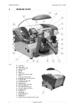
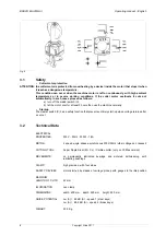
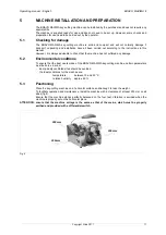
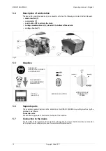
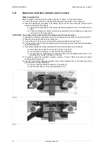
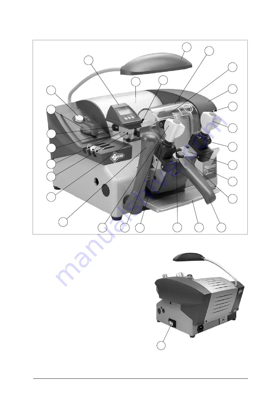
WORKING PARTS
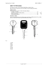
Fig. 5
A - cutting tool
B - tracer point
B1- tracer point support
C - master switch
D - carriage
E - clamp
F - clamp knob
H - transparent protective shield
I - brush
J - tracer point locking screw
J1- support/tracer point locking screw
K - calibration tabs
L - carriage movement lever
M - brush push button
N - chippings tray
O - tracer point regulating knob
O1- zero registration nut
P - motor start-up commutator
Q - carriage release push button
R - calibration drum
S - neon lamp
T - belt housing
U - double speed motor
V - carriage handle
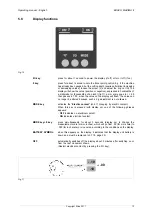
X - display unit
Z - protection from swarf produced by cutting
U
B1
J
P
O
H
A
I
F
E
Q
D
N
V
R
E
K
L
S
T
F
M
B
X
J1
O1
Z
C
Summary of Contents for Bravo Maxima II
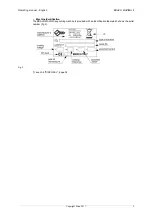
Page 1: ...Operating manual D432446XA vers 5 0 EN...
Page 4: ......


