


Operating manual - English
BRAVO MAXIMA II
Copyright Silca 2011
7
3
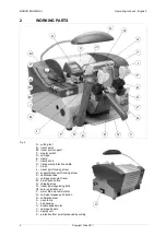
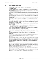
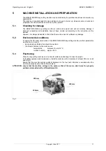
MACHINE DESCRIPTION
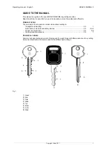
The BRAVO MAXIMA is a professional cutting machine for flat keys used with cylinder locks for doors,
cars and cruciform keys. The main parts of the machine are described below:
•
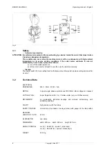
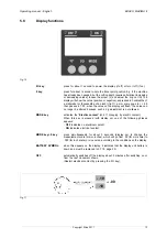
CONTROL PANEL
The control panel with 2 controls is located on the left-hand side of the BRAVO MAXIMA key-cutting
machine: the motor start-up switch (P), which also acts as speed commutator and the push button for
the brush (M) (fig. 5, page 6).
•
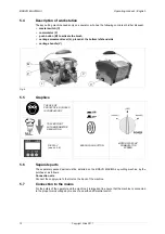
MOTOR AND TRANSMISSION UNIT
The motor (U) is located on the back of the BRAVO MAXIMA key-cutting machine, under the central
cover.
Motor speed is that more suitable for the materials to be cut. The transmission unit is placed to the right
of the motor.
By means of a belt under a protective cover (T), the transmission unit powers the movement of the brush
(I) and cutting tool (A).
•
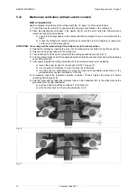
MOBILE UNIT
The mobile unit (D), consisting of the clamps, is fitted to the horizontal movement carriage controlled by
lever (L) and is provided with a handle (V) on the top of which can be found the carriage release button
(Q).
The carriage movement, along a double shaft on bearing brasses, allows high precision movements
which greatly facilitate all cutting operations.
The carriage is fully protected by the overhead cutting unit structure which avoids the accumulation of
dust and chippings from the work process.
The BRAVO MAXIMA is completely safe when used properly. However, for greater safety, two safety
devices are provided:
-
an automatic braking mechanism for the carriage slide, activated in the key-locking position.
-
an automatic carriage releasing device, linked to the return of the gauges to the idle position, which
activates the cutting tool only when the carriage is released.
The key-cutting machine is designed with a sloping protected surface along which swarf is channelled
into the special tray (N), easily removed for emptying and cleaning
•
CUTTING UNIT
The cutting unit contains the actual working parts of the BRAVO MAXIMA key-cutting machine, which
operate together to cut and finish keys "read" from the originals. The working parts are described below:
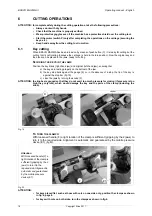
Brush
The brush (I) is used to eliminate burrs from the cuts and is made of non-abrasive material.
Cutting Tool
The cutting tool (A) is the part of the BRAVO MAXIMA used for cutting key blanks from the tracer point’s
reading of the cuts on the original key. The cutting tool is in HSS super rapid steel or hard metal and is
covered by a transparent plastic shield (H) which provides protection for the operator.
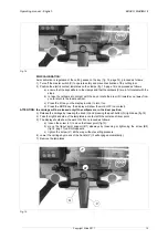
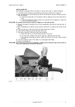
Tracer point
The tracer point (B) is placed on its own support (B1), to the left of the cutting tool. It has micrometric
regulation which makes it possible to adjust the cutting depth quickly and accurately. The tracer point
comes with an electronic device for zeroing the machine and shows the regulation values on the display.
The tracer point regulating knob (O) and the nut (O1) for registering zero are included in the unit. The
original key-reading unit is complete with the tracer point locking screw (J) and the screw which holds it
to the support (J1).
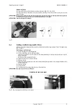
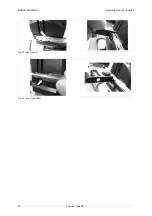
Clamps
The clamps of BRAVO MAXIMA key-cutting machine ensure perfect grip on keys (fig. 6, page 8).
The clamps are placed in front of the tracer point and cutting tool (E) respectively to grip the original key
and the key blank. With the clamps, cutting is rapid and precise for various types of keys and a wire
range of optional accessories can be used on the machine.
Anatomical knobs (F) with which to secure the keys are fitted on top of the clamps. The knobs are
designed so that only slight pressure is needed to give perfect grip on the keys.
On the lower side of the clamps are the calibration tabs (K). The rotating drum for the gauges (R) is
placed at the centre of the carriage, between the two clamps.
Illumination of the work area
In order to facilitate safe use of the BRAVO MAXIMA key-cutting machine, it has a fixed neon lamp (S)
that illuminates the work area and is switched on by means of the master switch (C).
Summary of Contents for Bravo Maxima II
Page 1: ...Operating manual D432446XA vers 5 0 EN...
Page 4: ......


