
Operating manual - English
BRAVO MAXIMA II
Copyright Silca 2011
33
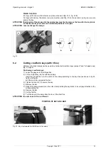
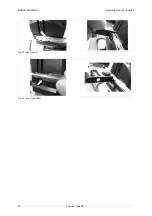
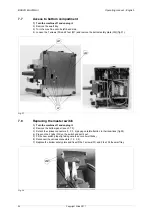
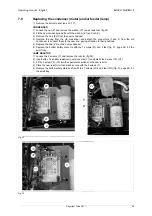
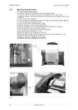
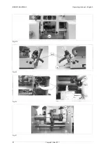
7.17
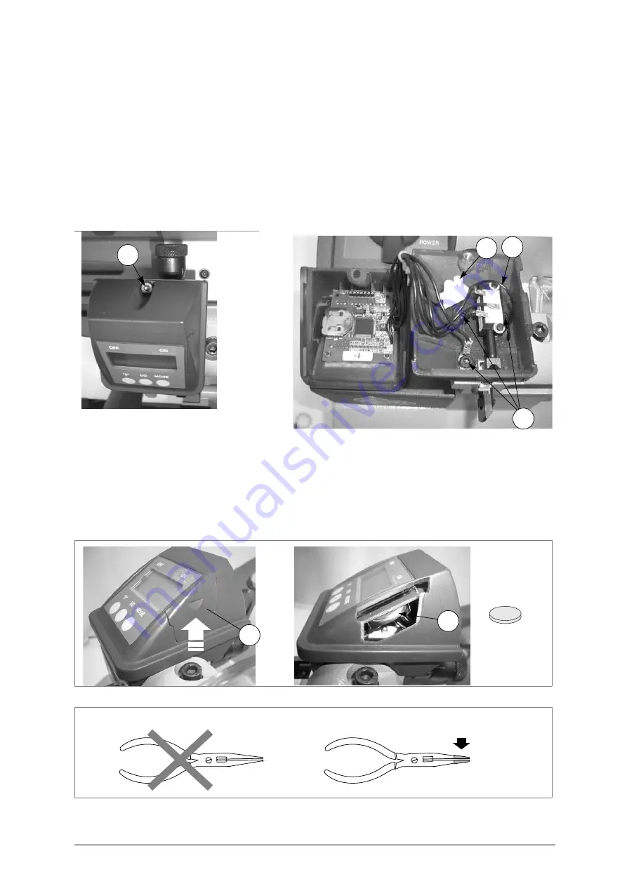
Replacing the Display unit
1) Turn the machine off and unplug it.
2) Loosen the screw (X1) and remove.
3) Pull the top part of the display out partially towards the front of the machine and raise.
4) Loosen the screw (X2) on the connector so that the wire (X3) is freed.
5) Loosen the 3 screws (B4) in order to remove the base of the display.
6) Fit the new display unit, first securing the new base with the 3 screws (B4), making sure you take the
wire (X3) through the special hole on the inside.
7) Replace the top part of the display, after connecting the wire (X3) to the connector, inserting it from
the front and pushing towards the back.
8) Tighten the screw (X1) to secure the top part of the display.
9) Check gauging with the electric contact (ch.5.11, page 14).
Fig. 52
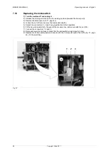
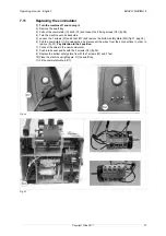
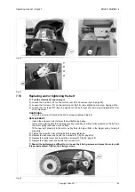
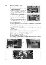
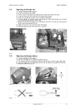
7.18
Replacing the Display battery
1) Turn the machine off and unplug it.
2) Raise the side flap(B5) on the display assembly and remove.
3) Use a long-pronged pincer insulated with adhesive tape (fig.54) to remove the spent battery (B6).
4) Use long-pronged pincers with insulated points to fit the new battery, paying attention to the poles.
5) Replace the flap (B5) into its seat.
Fig. 53
Fig. 54
X1
B4
X2
X3
B5
B6
-
+
NO!
YES!
insulated points
with adhesive tape
Summary of Contents for Bravo Maxima II
Page 1: ...Operating manual D432446XA vers 5 0 EN...
Page 4: ......


