


BRAVO MAXIMA II
Operating manual - English
2
Copyright Silca 2011
GENERAL INTRODUCTION
The BRAVO MAXIMA key-cutting machine has been designed according to the specifications of the
Machine Directives. From the design stage risks for the operator have been eliminated in all areas:
transport, key-cutting, regulation and maintenance.
Other risks have been eliminated by the use of protective devices for the operator.
The protective devices used are designed not to provoke further risks and, above all, they cannot be
ignored unless deliberately cut out. They do not hinder visibility of the work area.
A special adhesive label is attached to the machine warning the operator to use goggles during the
cutting operations, and this is strongly recommended in this manual.
The material used in the manufacture of this machine and the components employed during use of the
machine are not dangerous and their use complies with standards.
U
SE
The BRAVO MAXIMA must be installed and used in the way laid down by the manufacturer.
If the key-cutting machine is used differently or for purposes different from those described in this
manual, the customer will forego any rights he may have over SILCA S.p.A. Furthermore, unforeseen
danger to the operator or any third parties may arise from incorrect use of the machine.
Negligence in the use of the machine or failure on the part of the operator to observe the instructions
given in this manual are not covered by the guarantee and the manufacturer declines all responsibility
in such cases.
It is therefore indispensable to read the operating manual carefully in order to make the best use
of the BRAVO MAXIMA and benefit from its potential.
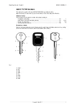
Instructions manual
The instructions manual provided with the machine is essential to its proper use and to carry out the
necessary maintenance.
We therefore recommend protecting the manual from damage in a safe sheltered place, easily to hand
for quick consultation.
F
URTHER
R
ISKS
There are no further risks arising from the use of the machine.
P
ROTECTION
AND
SAFETY
PRECAUTIONS
FOR
THE
OPERATOR
The BRAVO MAXIMA key-cutting machine is built entirely to standards. The operations for which it has
been designed are easily carried out at no risk to the operator.
The adoption of general safety precautions (wearing protective goggles) and observation of the
instructions provided by the manufacturer in this manual eliminate all human error, unless deliberate.
The BRAVO MAXIMA key-cutting machine is designed with features which make it completely safe in
all its parts.
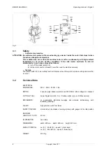
•
Power supply
The key-cutting machine is powered by electricity supplied through a separable earthed plug.
•
Start-up
The machine is turned on by means of the master switch located on the right-hand side. The switch has
a safety function that prevents untimely start-up when voltage returns after a cut-out.
•
Operation
The speed commutator activates the machine and allows selection of the required speed.
•
Illumination
The work area is illuminated by a neon lamp operated by means of the master switch.
•
Maintenance
The operations to regulate, service, repair and clean the machine have been devised in the simplest
and safest way possible. There is no danger of removable parts being re-placed wrongly or unsafely.
Summary of Contents for Bravo Maxima II
Page 1: ...Operating manual D432446XA vers 5 0 EN...
Page 4: ......


