Silca S.p.A. - OPERA-IV
6
TARATURA ASSIALE
Nella duplicatrice OPERA-IV la taratura assiale é fissa,
non necessita quindi di nessuna manutenzione da parte
dell’utilizzatore.
CONTROLLO TARATURA DELLA
PROFONDITÀ DI TAGLIO
Il controllo della taratura di profondità deve essere ese-
guito periodicamente per una perfetta efficienza della
macchina e ad ogni cambio della fresa (per usura o
sostituzione) o del tastatore.
PROCEDIMENTO:
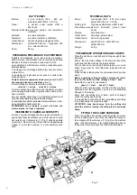
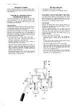
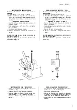
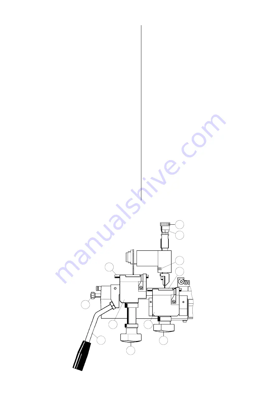
Sbloccare il morsetto mobile (M1) tirando il pomello (S)
verso sinistra; bloccare il morsetto in posizione orizzon-
tale spingendo il pomello (S) verso destra.
Inserire le spine di taratura (X) ("d" pag.2) sui morsetti e
bloccarle con le manopole (P) e (P1); appoggiare il
tastatore contro la spina, far ruotare la fresa a mano in
tutta la sua circonferenza e verificare che sfiori la spina
montata sul morsetto mobile (M1).
Se tale condizione non si verifica, agire come segue:
- Allentare il grano (E2); ruotando la ghiera (E3) si
effettua la regolazione sopra descritta.
- Ruotando la ghiera (E3) in senso orario, la fresa si
allontana dalla spina e viceversa.
- Ogni divisione del tamburo graduato é di 0,05 mm.
- Ottenuto lo sfioramento della fresa, serrare il grano
(E2) e azzerare il tastatore riportando l’indice di
riferimento del volantino (E4) in corrispondenza della
tacca sul tamburo graduato.
- Per fare questo tenere fermo con una mano la parte
zigrinata del volantino (E3) e con l’altra girare la
parte mobile del volantino (E4).
M
1
S
X
X
P
P
1
M
E
2
E
4
E
3
R
Fig. 6
SETTING SPACING
The spacing on the OPERA-IV is fixed.
It is therefore not necessary for the operator to set it.
CHECKING THE CUTTING DEPTH SETTING
To ensure perfect efficiency of the machine the cutting
depth setting must be checked periodically and every
time the cutting tool is changed (when it is worn or must
be replaced) or on changing the tracer point.
PROCEDURE:
Release the mobile clamp (M1) by pulling knob (S) to
the left; lock the clamp in a horizontal position by push-
ing the knob (S) to the right.
Insert the calibrating pins (X) (“d” on page 2) into the
jaws and secure with knobs (P) and (P1); bring the
tracer point into contact with the pin, turn the cutting tool
full circle by hand and check that it skims the pin in the
mobile clamp (M1).
If this is not the case, act as follows:
- Loosen the grub screw (E2); the adjustment
described above is carried out by turning the nut
(E3).
- Turning the nut (E3) clockwise distances the cutting
tool from the pin, and vice versa.
- The drum is graduated into 0,05 mm sections.
- When the cutting tool skims the pin, secure the grub
screw (E2) and zero the tracer point by taking the
reference notch on the handwheel (E4) up to the
notch on the graduated drum.
- To do this hold the knurled part of the handwheel
(E3) with one hand and with the other turn the
mobile part of the handwheel (E4).

