Optika
Operating manual - English
Copyright Silca 2017
17
Pump keys
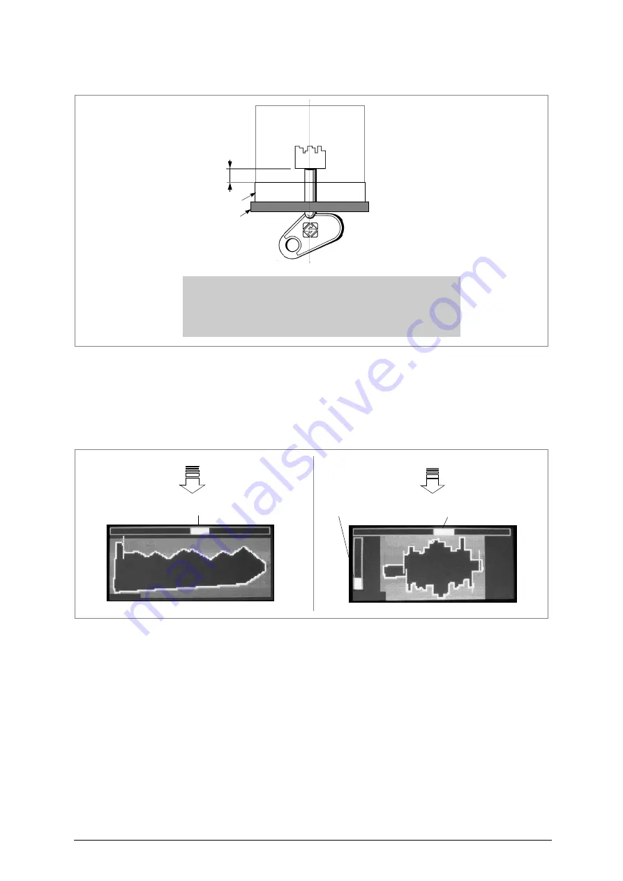
After inserting the key involved, the display will show a plan view of the key (turn the ENTER knob to
change the view from horizontal to vertical and vice versa). Make sure the stop detector line/pointer
(hatched) is the right position and that the top key alignment bar is as fine as possible (fig. 22).
6.1.2
STEP 1: VIEWING THE CUTS
•
If the key stop cannot be seen in the flat key view on the display, the pointer will flash and be
approximately in the centre of the display. Just push the key head slightly so that the key advances
well into the clamp.
•
If in the view of the key on the display (male and female bit) the left-hand bar (referred to inserted
key) is not fully upwards, try pushing the key head gently to insert the key into the clamp.
• When the fitting bar is fully up, do not push the key any further.
•
If the top bar shown on the display is not a fine line, turn the clamp slightly to the right or left until it
appears as required.
•
The better alignment, the better reading will be of stem or bit length.
light shade
illuminators
-
The bit must go past the illuminators
.
-
A minimum of 10 mm. of stem must be inserted
.
-
The key stem must be entirely surrounded by the light
shade device
.
min.
10 mm
devixe
key alignment bar
key alignment bar
L:2707
L:2419
key-fitting bar


