

REKORD AY
Operating manual - English
22
Copyright Silca 2019
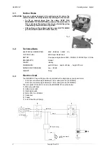
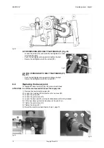
8.10
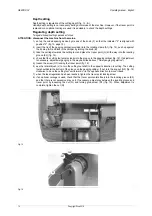
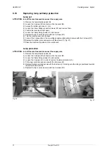
Replacing lamp set/lamp protection
Lamp set
ATTENTION: turn off the machine and disconnect the supply wire.
1) Remove the two protective pads (Q).
2) Loosen the 3 screws (M1) and remove the top cover (M).
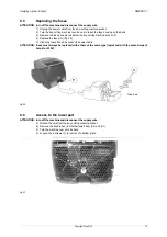
3) Access the bottom part (see ch. 8.6).
4) Loosen the 2 low voltage connector screws (Q1) and remove them.
5) Position the machine upright again.
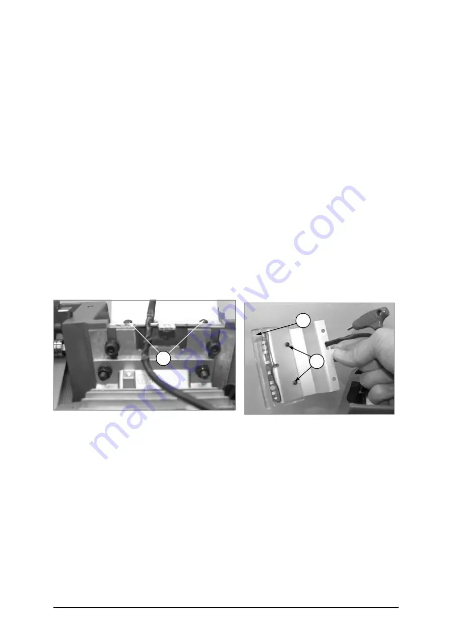
6) Loosen the 2 lamp fixing screws (L1) and remove.
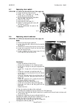
7) Replace the top cover and secure with the 3 screws (M1).
8) Turn the machine over onto its back.
9) Connect the 2 connectors in the low voltage supply outlet seat and secure with the 2 screws (Q1).
10) Replace the bottom grate and secure with the screws (Y) (fig. 27).
11) Place the machine in position on the work bench.
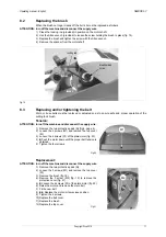
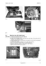
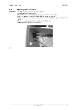
Lamp protection
ATTENTION: turn off the machine and disconnect the supply wire.
1) Remove the two protective pads (Q)
2) Loosen the 3 screws (M1) and remove the top cover (M).
3) Loosen the 2 lamp fixing screws (L1) and remove.
4) Loosen the 2 screws (L2) in order to remove the lamp protection (L3).
5) Fit the new protection and secure with the 2 screws (L2)
6) Replace the lamp unit and secure with the 2 screws (L1) making sure the wiring is positioned towards
the bottom of the machine.
7) Replace the top cover and secure with the 3 screws (M1).
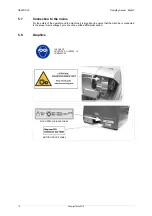
Fig. 36
Fig. 37
L1
L2
L3


