background image

Operating manual

Twister II NA

Copyright Silca S.p.A. 2015

16

8 MAINTENANCE

ATTENTION:  for repairs or replacement of parts for maintenance, the ‘CE’ mark is guaranteed 

only if original spare parts provided by the manufacturer are used.

Although the TWISTER II NA key-cutting machine does not require special maintenance, it is advisable to check 
and, if necessary, replace the parts subject to wear, such as: the belt (Section 8.1) and the lamp (Section 8.2). 
Replacement is simple and can be carried out by the operator.
CLEANING: keep the carriage and clamps free of chippings from the cutting operations by cleaning with a dry 
brush.

ATTENTION:  DO NOT USE COMPRESSED AIR!

ATTENTION:  to keep the machine well maintained we recommend using protective oil, e.g. 

WD40 or similar, applied to the burnished mechanical parts. This prevents oxidation of the 
parts in question (clamps, guides, carriages, etc.).

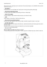
Before starting any type of maintenance (checks or replacements), read the instructions below:

•  never carry out maintenance or servicing with the machine switched on.
•  always unplug the machine prior to servicing.
•  follow all the instructions in the manual to the letter.
•  use original spare parts.

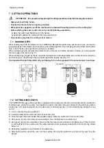
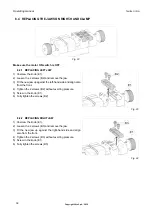
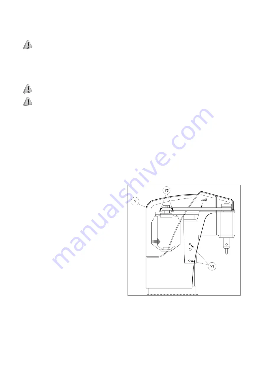
8.1  REPLACING THE BELT AND ADJUSTING TENSION

If the upper part of the machine vibrates, check the tension on the belt, as described below: 
1)  Turn off the master switch and unplug the machine.
2)  Loosen the four screws (Y1), knob (R) (Fig. 6 on 

page 7) and remove the upper casing (Y).

3)  Loosen (but do not remove) the four socket head 

screws (Y2) securing the motor.

4) a) tension:

increase belt tension by pushing the motor 
towards the back of the machine.

b) replacement:

loosen the belt by pushing the motor slightly 
towards the tracer point and cutting tool.

remove the belt and replace.

tighten the tension by pushing the motor towards 
the back of the machine.

5) Secure the motor by tightening the four socket 

head screws (Y2).

6)  Replace the upper casing (Y), secure with the four 

screws (Y1) and replace knob (R).

Fig. 18

Summary of Contents for Twister II NA

Page 1: ...Twister II NA Operating Manual Original Instructions D445453XA vers 1 0 EN...

Page 2: ...Ltd Plot no 37 Toy City GREATER NOIDA U P 201308 IMPORTANT NOTE in compliance with current regulations relating to industrial property we hereby state that the trade marks or trade names mentioned in...

Page 3: ...ND UTILIZATION 12 6 1 FITTING AND REGULATING THE TOOLS 12 6 2 CALIBRATION OF THE CUTTER AND TRACER 12 7 CUTTING OPERATIONS 13 7 1 GAUGING KEYS 13 7 2 CUTTING DIMPLE KEYS 13 7 3 CUTTING LASER SIDEWINDE...

Page 4: ......

Page 5: ...ransport and handling Ch 1 Description of machine and safety devices Ch 2 3 4 Proper use of machine Ch 5 6 7 Maintenance Ch 8 9 10 Technical terms Common technical terms are used in this manual To ass...

Page 6: ...to observe the instructions given in this manual are not covered by the guarantee and the manufacturer declines all responsibility in such cases IT IS OBLIGATORY to read the manual carefully before us...

Page 7: ...erating manual Twister II NA Copyright Silca S p A 2015 3 Machine identification The TWISTER II NA key cutting machine is provided with an identification label which shows the serial number Fig 2 Fig...

Page 8: ...ions and warnings for transportation Use of the packing box whenever the machine is transported will avoid knocks or bumps which could cause damage 1 3 UNPACKING To remove the machine from the packing...

Page 9: ...eatures great versatility in cutting keys of different types without the need to replace the clamp or apply fixed adapters TWISTER II NA cuts the following types of keys DIMPLE KEYS with flat cuts LAS...

Page 10: ...to the cutter and chips LAMP Placed directly on the machine it illuminates the work area TRACER POINT ADJUSTING RING NUT Ensures perfect depth alignment of the tools and makes it possible to adjust f...

Page 11: ...jaw knob E1 right hand jaw knob G protective shield H clamp carriage locking knobs H1 clamp group locking knob H2 locking knob tracer shaft I vertical carriage lever Z axis L sleeve cutting tool and t...

Page 12: ...xis on bars longitudinal and transversal axes on ball guides Clamp universal interchangeable Travel X axis lower 1 6 40 mm Y axis upper 2 0 50 mm Z axis vertical 1 2 30 mm Dimensions width 9 8 250 mm...

Page 13: ...3 2 ELECTRIC CIRCUIT The main parts of the electrical and electronic circuit on the TWISTER II NA are listed below 1 Machine plug 2 Fuses 8 Amp delayed 120V 3 Master switch 4 Led 4 5W 120V 5 Motor st...

Page 14: ...upplied for use with the machine or for servicing tools Allen keys and adapters The accessories provided are CUTTING TOOL for dimple keys 3 mm ALLEN KEY TRACER POINT for dimple keys STEEL TIP STOP BAR...

Page 15: ...ain parameters must be borne in mind damp badly ventilated sites should be avoided the ideal conditions for the machine are between 50 and 104 F 10 and 40 C relative humidity approximately 60 5 3 POSI...

Page 16: ...o the right hand sleeve and secure by tightening the grub screw M1 Releasing the tools Unscrew the grub screw M and M1 to remove the tracer point and cutting tool from the sleeves M M1 Fig 10 6 2 CALI...

Page 17: ...lots on the clamp and load the key into the jaw so that the tip of the key rests against the tip stop bar Fig 13 It is important that both the pattern key and the key to be cut are gauged in the same...

Page 18: ...escribed earlier 3 Using lever I lower the Z axis until the tracer rests lightly on a CUT portion of the pattern key 4 While maintaining light contact tighten the Z axis locking knob R to secure the Z...

Page 19: ...t and gauge the pattern key as described in section 7 3 4 Secure the adapter and key by tightening knob E and E1 Fig 16 7 5 CUTTING KEYS FOR FICHET The clamp can also be used to cut keys for FICHET H...

Page 20: ...Before starting any type of maintenance checks or replacements read the instructions below never carry out maintenance or servicing with the machine switched on always unplug the machine prior to serv...

Page 21: ...ING AND REPLACING THE FUSES The fuses should always be checked with a continuity measuring instrument tester ohmeter multimeter etc as a visible check may not reveal an electrical fault Fuses must alw...

Page 22: ...ainst the left hand side and align also from the front 4 Tighten the 2 screws B2 without exerting pressure 5 Screw in the knob E1 6 Fully tighten the screws B2 Fig 23 8 4 2 REPLACING RIGHT JAW 1 Unscr...

Page 23: ...ful noxious substances it is included in the lists of the appendices to current regulations in Italy and the European Union for waste disposal INFORMATION TO USERS Under the terms of Directive 2012 19...

Page 24: ...safety for the operator and machine any job not specified in this manual should be carried out by the manufacturer 10 1 HOW TO REQUEST SERVICE The limited warranty period for the TWISTER II NA key cut...

Reviews: