


Operating manual
Twister II NA
Copyright Silca S.p.A. 2015
4
1
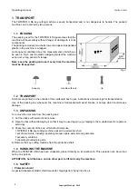
TRANSPORT
The TWISTER II NA key-cutting machine is easily transported and is not dangerous to handle. The packed
machine can be carried by two persons.
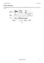
1.1 PACKING
The packing used for the TWISTER II NA guarantees that the
machine will travel safely without danger of damage to it or its
components.
The packing comprises two shells, lower and upper in expanded
plastic in the machine is wrapped.
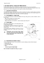
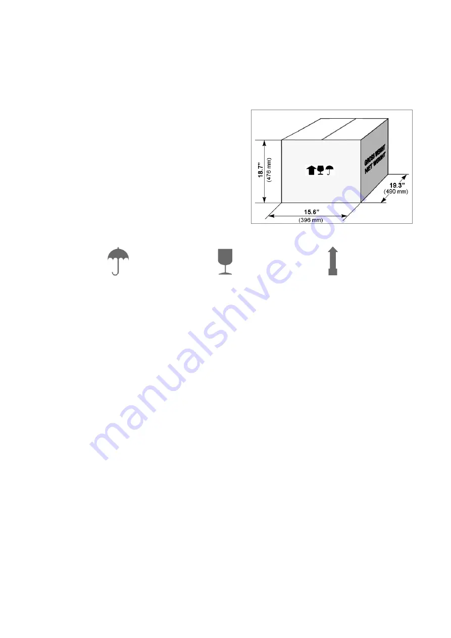
A strong outer cardboard box, the measurements of which can
be seen in Fig. 3 and the plastic wrapping protect the machine
even over a long period of storage.
Note: keep the packing and use it every time the machine
must be transported.
Fig. 3
Keep dry
Handle with care
Up
1.2 TRANSPORT
Symbols are printed on the outside of the cardboard box to give instructions and warnings for transportation.
Use of the packing box whenever the machine is transported will avoid knocks or bumps which could cause
damage.
1.3 UNPACKING
To remove the machine from the packing box:
1) Cut the straps with scissors and remove.
2) Open the box without damaging it so that it may be used again (e.g. shipping to the manufacturer for repairs or
servicing).
3) Check the contents of the box, which should comprise:
1 TWISTER II NA key-cutting machine packed in a protective shell.
1 set of documents, including: operating manual, spare parts list and guarantee.
1 accessory container.
1 separate grounded plug wire.
4) Remove the key-cutting machine from the protective shell.
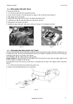
1.4 HANDLING THE MACHINE
When the TWISTER II NA has been unpacked, place it directly on its workbench. This operation can be carried
out by one person.
ATTENTION: hold the base, and no other part, to lift and carry the machine.
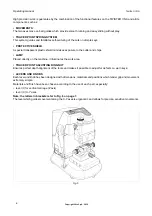
1.5 SAFETY
• Protective shield
A special transparent plastic shield prevents chippings from
fl
ying into the air.


