Control Panel Installation
151430
4-33
4.13.1.2 Class A Notification Wiring
You must use an appliance from the list of compatible appliances in the Appendix at the back
of this manual.
To install a Class A notification appliance circuit:
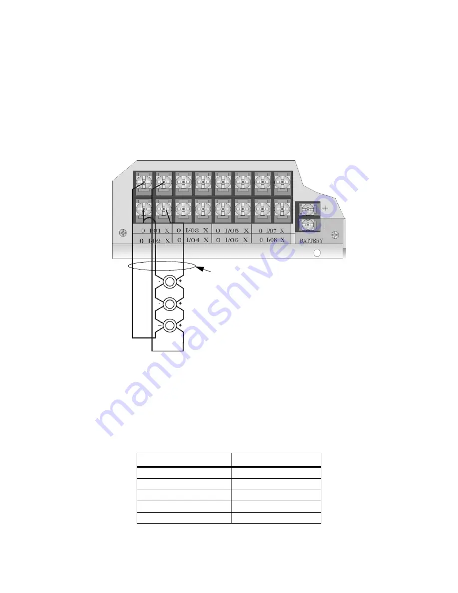
1. Wire the Class A notification appliances as shown in Figure 4-33.
2. Configure the circuit for Class A in programming (see Section 9.5).
Figure 4-33 Class A Notification Appliance Circuit Configuration
Note: In programming any point that uses multiple Flexput circuits, the lowest Flexput circuit number is used to
refer to the circuit pair. For example, Figure 4-33 uses both Flexput circuit 1 and 2, so in programming it
would be referred to as point 1.
Maximum voltage drop is 3V per Class A circuit. See Table 4-4
Table 4-4 Maximum Impedance Class A
Current
Maximum Impedance
1.0A
3
Ω
1.5A
2
Ω
2.0A
1.5
Ω
2.5A
1.2
Ω
3.0A
1.0
Ω
Supervised
Power Limited
Regulated 24 VDC
3A per Circuit, 9A max Combined
Summary of Contents for IFP-2000
Page 2: ......
Page 12: ...IFP 2000 Installation Manual viii...
Page 22: ...IFP 2000 Installation Manual 1 10 151430...
Page 26: ...IFP 2000 Installation Manual 2 4 151430...
Page 31: ...Before You Begin Installing 151430 3 5 Figure 3 1 Wire Routing Example...
Page 100: ...IFP 2000 Installation Manual 5 14 151430...
Page 194: ...IFP 2000 Installation Manual 10 20 151430...
Page 210: ...IFP 2000 Installation Manual 12 8 151430...
Page 230: ...IFP 2000 Installation Manual A 14...
Page 232: ...IFP 2000 Installation Manual B 2 151430...
Page 236: ......
Page 237: ......


