IFP-2000 Installation Manual
4-34
151430
4.13.2 Conventional Input Switch Circuits
This section of the manual explains how to install conventional initiating devices for Class A
(Style D) or Class B (Style B) configurations.
4.13.2.1 Class B Inputs
You can connect conventional Class B switches, such as waterflow switches and pull stations,
directly to the Flexput circuits of the control panel.
To install a Class B switch:
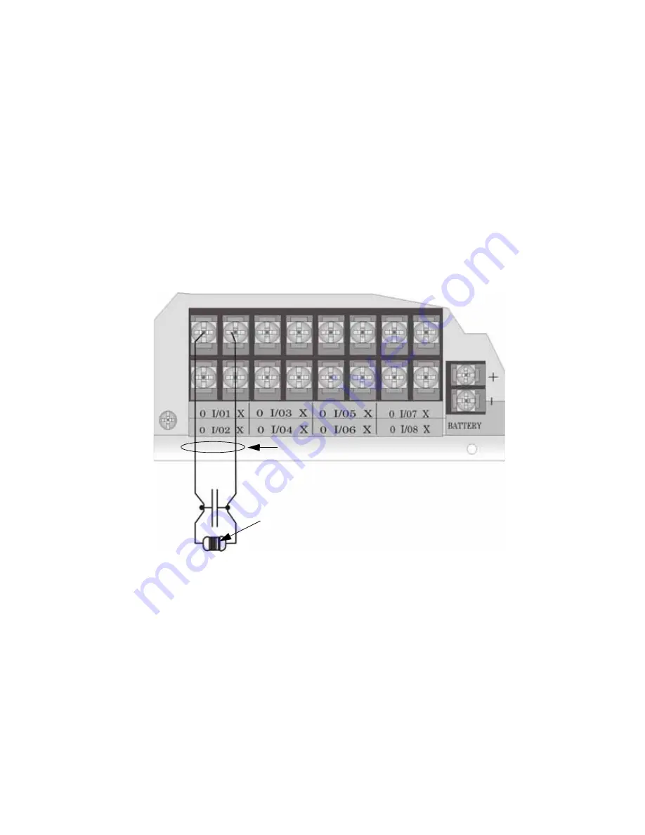
1. Wire the Class B switch as shown in Figure 4-34.
2. Configure the circuit through programming (see Section 9.5).
Figure 4-34 Class B Input Switches
Supervised
Power Limited
Maximum Impedance per
Circuit is 50
Ω
UL Listed
EOL
Model
Summary of Contents for IFP-2000
Page 2: ......
Page 12: ...IFP 2000 Installation Manual viii...
Page 22: ...IFP 2000 Installation Manual 1 10 151430...
Page 26: ...IFP 2000 Installation Manual 2 4 151430...
Page 31: ...Before You Begin Installing 151430 3 5 Figure 3 1 Wire Routing Example...
Page 100: ...IFP 2000 Installation Manual 5 14 151430...
Page 194: ...IFP 2000 Installation Manual 10 20 151430...
Page 210: ...IFP 2000 Installation Manual 12 8 151430...
Page 230: ...IFP 2000 Installation Manual A 14...
Page 232: ...IFP 2000 Installation Manual B 2 151430...
Page 236: ......
Page 237: ......


