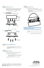
ValeoView™ Housing
Quick Install Guide
See over.
Overview
Your ValeoView™ camera is comprised of a housing, a gimbal, and a quick
change lens. The ValeoView camera is designed to be flush or surface
mounted indoors on a wall or ceiling.
Follow these steps to get started with your new ValeoView camera:
Step
1
Install the housing (orange box). Follow the instructions in this guide.
Step 2
Install the gimbal. Refer to the ValeoView Gimbal Quick Install Guide that
comes with the gimbal (yellow box).
Step 3
Install the lens. Refer to the Lens Quick Install Guide that comes with the
lens (blue box).
Step 4
Install the enclosure cover. Follow the instructions in this guide.
Important safeguards
Installation and servicing should be done by certified technicians to
conform to all local codes and to maintain your warranty.
Before you begin
Unpack everything. The ValeoView packing box should include one
ValeoView enclosure and this Quick Install Guide.
If any parts are missing or damaged, contact the dealer you purchased the
camera from, or call Silent Witness Customer Service.
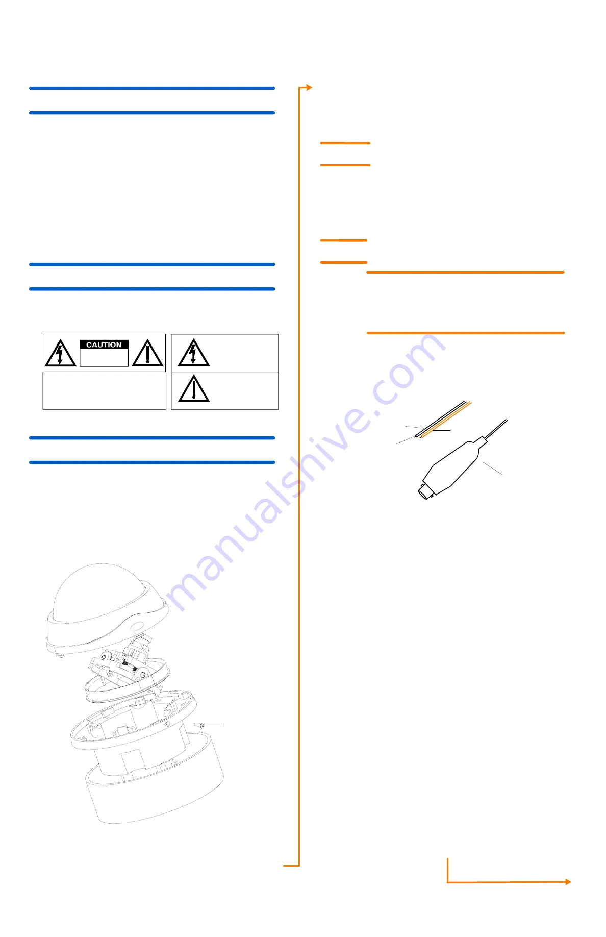
Figure 1
Installation components
This symbol indicates
that important operating
and maintenance
instru
this unit.
This symbol indicates
that dangerous voltage
constituting a risk of
electric shock is present
within this unit.
CAUTION: TO REDUCE THE RISK OF ELECTRIC
SHOCK,
DO NOT REMOVE THE COVER.
NO USER-SERVICEABLE PARTS INSIDE
REFER SERVICING TO QUALIFIED SERVICE
PERSONNEL
RISK OF ELECTRIC
SHOCK
DO NOT OPEN
ctions accompany
Gimbal (shipped separately)
Skirt - use with surface mount installation
Base
Dome enclosure
1/4” screw (for
securing the dome to
the base)
Equipment required
You will require the following to complete the installation:
•
Phillips screwdriver.
•
Mounting screws. Use mounting screws appropriate to your
installation.
Prepare the base
1.
Remove the 1/4 inch screw on the side of the housing. Set aside.
2.
Remove the dome by turning it counterclockwise until it is free of
the base.
3.
Remove the two 3/4 inch screws securing the base to the skirt.
4.
Remove the base from the skirt by pulling it towards you.
Wire the camera
To connect the video and power cables:
1.
Connect the power cable to the power supply.
2.
Connect the video cable to the video input on a monitor.
Figure 2
Wiring connections
Note
For secure installations, surface-mounted cables should be
protected by plastic or metal cable covers as shown in this
diagram.
Cable guidelines
Step
1
Step
2
WARNING!
The use of a CSA Certified/UL Listed Class 2
power supply is required to ensure compliance
with electrical safety standards.
Cables
Video: female
BNC wire
Power: Flying lead
Red +
Black -
Power supply cable maximum length (feet/meters)
Cameras with AC/DC power supplies
Wire gauge
Total
load
Power
supply
24
AWG
22
AWG
18
AWG
16
AWG
2.5 W
15 VDC
260/79
415/126
1055/321
1680/512
2.5 W
24 VAC
608/185
980/299
2515/767
3930/1198
3.5 W
15 VDC
60/18
100/30
250/76
400/122
3.5 W
24 VAC
470/143
760/232
1926/587
3065/934
Note
Calculations are based on an unregulated linear power supply which would be the
worst case. Using a regulated or switching power supply can increase the cable distance. Silent
Witness recommends using a CSA Certified/UL listed Class 2 power supply to ensure
compliance with electrical safety standards.
Coaxial video cable maximum length (feet/meters)
Cable type
RG-59
RG-6
RG-11
Wire gauge
23 AWG*
18 AWG*
16 AWG*
Maximum length
750/229
1500/457
2000/610
* Copper clad steel core, 95% braided shield


