


Si53xx-RM
Rev. 0.52
13
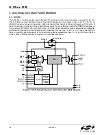
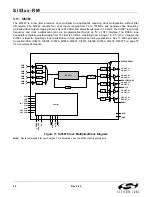
A wide range of settings are available, but they are a subset of the frequency plans supported by the Si5323 and
Si5366 jitter-attenuating clock multipliers. The Si5325 and Si5367 are microprocessor-controlled clock multipliers
that can be controlled via an I
2
C or SPI interface.
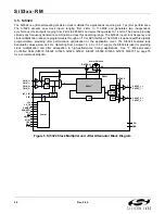
These devices accept clock inputs ranging from 10 MHz to 710 MHz and generate multiple independent,
synchronous clock outputs ranging from 10 MHz to 945 MHz and select frequencies to 1.4 GHz. The Si5325 and
Si5367 support a subset of the frequency translations available in the Si5319, Si5324, Si5326, Si5327, Si5368, and
Si5369 jitter-attenuating clock multipliers. The Si5325 and Si5367 can accept input clocks at different frequencies
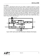
and generate output clocks at different frequencies. The Si5322, Si5325, Si5365, and Si5367 support a digitally
programmable loop bandwidth that ranges from 150 kHz to 1.3 MHz. No external components are required for
these devices. LOS and FOS monitoring is available for these devices, as described above.
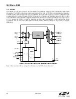
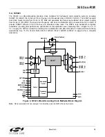
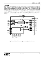
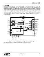
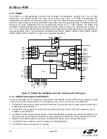
The Si5374 and Si5375 are quad DSPLL versions of the Si5324 and Si5319, respectively. Each of the four
DSPLLs can operate at completely independent frequencies. The only resources that they share are a common
I
2
C bus and a common XA/XB jitter reference oscillator. The Si5375 consists of four one-input and one-output
DSPLLs. The Si5374 consists of four two-input and two-output DSPLLs with very low loop bandwidth.
The Any-Frequency Precision Clocks have differential clock output(s) with programmable signal formats to support
LVPECL, LVDS, CML, and CMOS loads. If the CMOS signal format is selected, each differential output buffer
generates two in-phase CMOS clocks at the same frequency. For system-level debugging, a PLL bypass mode
drives the clock output directly from the selected input clock, bypassing the internal PLL.
Silicon Laboratories offers a PC-based software utility, DSPLL
sim
, that can be used to determine valid frequency
plans and loop bandwidth settings for the Any-Frequency Precision Clock product family. For the microprocessor-
controlled devices, DSPLL
sim
provides the optimum PLL divider settings for a given input frequency/clock
multiplication ratio combination that minimizes phase noise and power consumption. Two DSPLLsim configuration
software applications are available for the 1-PLL and 4-PLL devices, respectively. DSPLL
sim
can also be used to
simplify device selection and configuration. This utility can be downloaded from
http://www.silabs.com/timing
.
Other useful documentation, including device data sheets and programming files for the microprocessor-controlled
devices are available from this website.
Summary of Contents for Si5316 Series
Page 2: ...Si53xx RM 2 Rev 0 52 ...
Page 110: ...Si53xx RM 110 Rev 0 52 Figure 48 sfout_5 LVPECL Figure 49 sfout_6 CML ...
Page 111: ...Si53xx RM Rev 0 52 111 Figure 50 sfout_7 LVDS ...
Page 127: ...Si53xx RM Rev 0 52 127 Figure 66 155 52 MHz In 622 08 MHz Out Loop BW 7 Hz Si5324 ...
Page 128: ...Si53xx RM 128 Rev 0 52 Figure 67 19 44 MHz In 156 25 MHz Out Loop BW 80 Hz ...
Page 129: ...Si53xx RM Rev 0 52 129 Figure 68 19 44 MHz In 156 25 MHz Out Loop BW 5 Hz Si5324 ...
Page 131: ...Si53xx RM Rev 0 52 131 Figure 70 61 44 MHz In 491 52 MHz Out Loop BW 7 Hz Si5324 ...
Page 132: ...Si53xx RM 132 Rev 0 52 Figure 71 622 08 MHz In 672 16 MHz Out Loop BW 6 9 kHz ...
Page 133: ...Si53xx RM Rev 0 52 133 Figure 72 622 08 MHz In 672 16 MHz Out Loop BW 100 Hz ...
Page 134: ...Si53xx RM 134 Rev 0 52 Figure 73 156 25 MHz In 155 52 MHz Out ...
Page 139: ...Si53xx RM Rev 0 52 139 Figure 78 86 685 MHz In 173 371 MHz Out ...
Page 140: ...Si53xx RM 140 Rev 0 52 Figure 79 86 685 MHz In 693 493 MHz Out ...
Page 142: ...Si53xx RM 142 Rev 0 52 Figure 81 10 MHz In 1 GHz Out ...
Page 174: ...Si53xx RM 174 Rev 0 52 Figure 99 Si5374 Si5375 DSPLL A ...
Page 175: ...Si53xx RM Rev 0 52 175 Figure 100 Si5374 Si5375 DSPLL B ...
Page 176: ...Si53xx RM 176 Rev 0 52 Figure 101 Si5374 Si5375 DSPLL C ...


