Attention: Under normal conditions, a photovoltaic module is likely
to experience conditions that produce more current and/or voltage
than reported at standard test conditions. Accordingly, the values
of ISC and VOC marked on this module should be multiplied by a
factor of 1.25 when determining component voltage ratings,
conductor ampacities, fuse sizes, and size of controls connected
to the PV output.
Attention: Refer to Section 690-8 of the National Electrical Code
for an additional multiplying factor of 125 percent (80 percent
derating) which may be applicable.
For field connections, use minimum No. 10 AWG copper wires insulated
for a minimum of 194°F / 90 ºC.
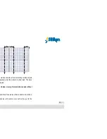
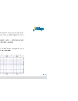
Once the modules are connected in series to obtain the correct input
voltage for each type of inverter it is essential that protection fuses are
located between the inverter and each series. These fuses will facilitate
maintenance and control tasks, but they will mainly protect the series
from each other should the polarity of one of the series of modules be
incorrectly connected.
Series fuse (overcurrent protection) rating of
15
A.
Protection fuses
14
Instructions for using photovoltaic modules
!
!
Summary of Contents for Photovoltaic
Page 1: ...use...
Page 12: ...11 tion Operation with the cell in the shade...
Page 43: ...Notes Instructions for using photovoltaic modules...
Page 44: ......


