Copyright Donald W Thomas, K5ZRQ
9
6.0 PCB LAYOUT:
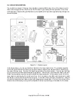
The PCB is mounted on the back wall of the amplifier. It contains the Receive Preamplifier Q1,
Transmit detector Q2, Power Amp relay driver Q3, Preamp relay driver Q4, and Relay K2 for switching
the preamp in and out of the circuit. There are 12 points shown in the drawing by a number inside a
circle. These points are connections from the PCB to various points in the LA-600 as indicated by the
labeling.
Figure 6-1 PCB
The wire connections to the PCB are as listed below:
1. Wire from PCB to relay K2 NO contact.
2. Connects to RF Input Jack.
3. Connects to Delay switch SSB contact.
4. Connects one end of R42, the other end of R42 is connected to the RF Output Jack.
5. Connects to the front panel meter.
6. Connects to Preamp switch.
7. Connects to Preamp switch.
8. Connects to the common contact of the Mode switch.
9. Connects to the +16V line.
10. Wire from PCB to relay K2 NC contact.
11. Connects to Relay K1A NC contact.
12. Connects to Preamp switch.
13. Hole on PCB ground trace that is unused.

