background image

13 


Thermistor Field Testing 

Use the guide below to test if a thermistor (temperature probe) is functioning properly. See the replacement parts list for 

part number information. Table 2 is valid for all thermistors listed on table 1.  


Establish Thermistor Temperature 

  Check the display’s temperature reading. 

  If a thermometer is available, use it to confirm the display’s 

temperature reading by taking the temperature at the 

thermistor.  

  If the previously stated tasks are unavailable, then use any 

reasonable means to estimate the thermistors temperature. 

See form M164 for ice bath method. (ice water is 32 

°

F) 


Multimeter Set-up 


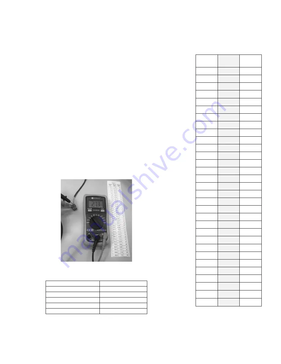
Use a multimeter and set it to the resistance (Ω) setting. See 

Figure 1. 

  Disconnect the thermistor from the controller, then connect the 

multimeter to the thermistor. See Figure 1. 

  Check and compare the multimeter’s reading to Table 1. 


Analyze Results 

  If the resistance and temperature are similar, then the 

thermistor is working properly and does not need to be 

replaced. 

  If the resistance and temperature are not similar or the 

resistance’s value is not on Table 1, then the thermistor is not 

working properly and needs to be replaced. 

  If the resistance reads over-limit, then the thermistor is not 

working properly and needs to be replaced. 


Figure 1 


Table 1 

Thermistor Description 

Part Number 

60” black 

46128 

120” black 

46141 

60” green 

46127 

120” green 

46140 

96” black 

38822 


Table 2 

Temp 

(

°

F)


Ohms  

(kΩ)


Temp 

(

°

C)


-4.0 

67.8 

-20 

-0.4 

61.5 

-18 

3.2 

56.0 

-16 

6.8 

51.0 

-14 

10.4 

46.5 

-12 

14.0 

42.5 

-10 

17.6 

38.8 

-8 

21.2 

35.4 

-6 

24.8 

32.4 

-4 

28.4 

29.7 

-2 

32.0 

27.3 

35.6 

25.0 

39.2 

23.0 

42.8 

21.2 

46.4 

19.5 

50.0 

18.0 

10 

53.6 

16.6 

12 

57.2 

15.3 

14 

60.8 

14.1 

16 

64.4 

13.0 

18 

68.0 

12.1 

20 

71.6 

11.2 

22 

75.2 

10.4 

24 

78.8 

9.6 

26 

82.4 

8.9 

28 

86.0 

8.3 

30 

89.6 

7.7 

32 

93.2 

7.2 

34 

96.8 

6.7 

36 

100.4 

6.3 

38 

104 

5.8 

40 


P/N 45810 - Rev C 


Summary of Contents for SKRM48-EGUS1

Page 1: ...otice Marmon Foodservice Technologies 355 Kehoe Blvd Carol Stream IL 60188 Contact 800 328 3329 Silverking com Technical Manual and Replacement Parts List Refrigerated Glass Door Merchandiser MODELS S...

Page 2: ...uired for normal operation If the supply cord is damaged it must be replaced by the manufacturer its service agent or similarly qualified persons in order to avoid a hazard This refrigeration unit is...

Page 3: ...frost refrigerator freezer Do not puncture refrigeration tubing Caution Risk of fire or explosion Flammable refrigerant used Consult repair manual owner s guide before attempting to service this produ...

Page 4: ...for example open flames an operating gas appliance or an operating electric heater Do not pierce or burn Be aware that refrigerants may not contain an odor WARNING Keep any required ventilation openin...

Page 5: ...ion to installing the Shelves level you have the option of installing the Shelves at a slant to better display your merchandise To do this simply install the rear Shelf Supports a few notches higher o...

Page 6: ...lly toxic or flammable atmospheres Ensure that the leak detection equipment being used is suitable for use with all applicable refrigerants i e non sparking adequately sealed or intrinsically safe Pre...

Page 7: ...king Discharge capacitors in a way that won t cause any spark using a Supco CapDis tool That no live electrical components and wiring are exposed while charging recovering or purging the system that t...

Page 8: ...be removed extinguished If a leakage of refrigerant is found which requires brazing all of the refrigerant shall be recovered from the system or isolated by means of shut off valves in a part of the...

Page 9: ...pt in an appropriate position according to the instructions WARNING Ensure that the REFRIGERATING SYSTEM is earthed prior to charging the system with refrigerant WARNING Label the system when charging...

Page 10: ...ne hour to respond to a control setting adjustment Lights There is an on off switch for the lights on the right front end of the light shroud Defrost Your Silver King refrigerator is an automatic defr...

Page 11: ...10...

Page 12: ...8822 15 CONDENSER 24425 SK 16 FAN MOTOR CONDENSER 115V 37736 17 TEMPERATURE CONTROL ELECTRONIC PROGRAMMED 47270 SK 18 COMPRESSOR KIT R290 W ELECTRICALS AND DRIER 115V 60HZ 11700 1 19 ELECTRICAL KIT RE...

Page 13: ...12...

Page 14: ...pare the multimeter s reading to Table 1 Analyze Results If the resistance and temperature are similar then the thermistor is working properly and does not need to be replaced If the resistance and te...

Page 15: ...Technical Manual Warranty excludes consumables or replacement components such as shelving trays gaskets etc Warranty excludes interior liner or exterior shell Condensing coils must be cleaned at regu...

Page 16: ...cluded from reimbursement Use of non OEM parts may at Silver King s discretion void this warranty If approved warranty credit for non OEM parts will be issued at the OEM cost Replacement parts sold se...

Page 17: ...ject to change without notice Payments via credit card are subject to a 3 5 surcharge Any and all environmental attributes including environmental offset credit rights with respect to Silver King refr...

Reviews: