


4
1
2
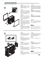
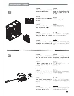
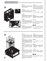
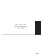
Please remove the 6 screws on the
panels with screw driver , then pull
upward the panels to remove
outward from chassis.
Открутите
отверткой
6
шурупов
на
боковых
панелях
и
поднимите
рычаг
быстрого
освобождения
,
как
показано
на
рисунке
,
затем
поднимите
вверх
боковые
панели
и
выньте
их
из
корпуса
.
側面パネルのネジ6本をドライバーで
外し、
クイックリリースレバーを図のよ
うに引き上げ、側面パネルを引き上げ
てケースから外します。
스큐류 드라이버를 이용해, 사이드
패널에 있는 6개의 나사를 제거한 후,
퀵 릴리즈 레버를 그림과 같이 들어
올립니다. 이후, 사이드 패널을 위로
올려 케이스에서 제거합니다.
6 Schrauben, die für Befestigung
des Panels sind , mit Schraubzieher
abschrauben.Wieder gemäss Bild
das Lever nach oben ausziehen
und das Panel ausnehmen.
veuillez retirer les 6 vis des panneaux
latéraux avec un tournevis et
soulevez le levier come montré,
puis soulevez les panneaux latéraux
pour les sortir du boîtier.
Por favor, quite 6 tornillos de los
paneles laterales con el destornilladory
accione la palanca de extracción
rápida como se muestra, luego
levante los paneles laterales para
quitarlos del chasis.
Rimuovere con un cacciavite le
sei viti dai pannelli e spostare la
leva di apertura come mostrato;
rimuovere in seguito i pannelli
dal telaio.
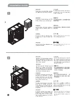
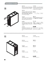
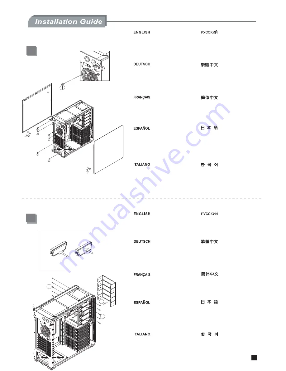
Please release the screws on 5.25” device
cover, then press the area as shown to
remove it outward from chassis.
Открутите
шурупы
на
крышке
отсека
5,25-
дюймового
устройства
,
затем
нажмите
на
указанную
область
и
выньте
отсек
из
корпуса
.
请用螺絲起子拆掉鎖固5.25”擋板的螺絲,
並按壓側邊的鎖扣後將擋板取下。
5.25”ドライブベイカバーからネジを外し、
図示された部分を押してケースから外側
に外します。
5.25” 드라이브 베이 커버에서 나사를
제거한 후, 그림에서 보이는 부분을 누
르고, 케이스 밖으로 제거합니다.
bitte die Schrauben an 5.25” Abdeckung
mit Schraubzieher abschrauben.den
Bereich wie angezeigt drücken,um
Panel auszunehmen.
Veuillez retirer les vis du cache de la
baie 5.25”, puis appuyez sur la zone
désigné pour le sortir du boîtier.
Quite los tornillos de la cubierta de
la bahía de dispositivos de 5.25”,
luego presione el área como se
muestra para sacarla del chasis.
Dopo aver rimosso le viti, estrarre,
esercitando una lieve pressione,
il rivestimento del dispositivo 5.25’’
come mostrato.
請以螺絲起子卸下鎖固側板的6顆螺絲,
再依圖示將拉桿向上扳開後取出側板。
OFF
ON
1
1
2
用螺絲起子拆掉鎖固5.25"擋板的螺絲,
並按壓側邊的鎖扣後將擋板取下。
请以螺丝起子卸下锁固侧板的6颗螺丝,
再依图示将拉杆向上扳开后取出侧板。
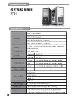
Summary of Contents for SST-FT01B
Page 1: ...MANUAL FORTRESS SERIES FT01...
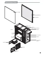
Page 11: ......
Page 12: ...July 2008 Issue date G11207500...


