Smart Machine Smart Decision
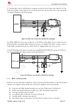
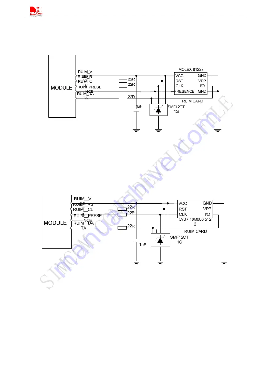
It is recommended to use an ESD protection component such as ON (http://onsemi.com) SMF12CT1G. That
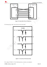
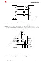
the RUIM peripheral circuit should be close to the RUIM card socket. The reference circuit of the 8-pin RUIM
card holder is illustrated in the following figure.
Figure 24: Reference circuit of the 8-pin RUIM card holder
The RUIM_PRESENCE pin is used for detection of the RUIM card hot plug in. User can select the 8-pin
RUIM card holder to implement RUIM card detection function. AT command “AT+CSDT” is used to enable or
disable RUIM card detection function. For details of this AT command, please refer to
document [1]
.
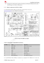
If the RUIM card detection function is not used,
user can keep the RUIM_PRESENCE pin open. The reference
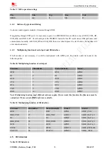
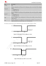
circuit of 6-pin RUIM card holder is illustrated in the following figure.
Figure 25: Reference circuit of the 6-pin RUIM card holder
4.7.2.
RUIM Card Design Guide
RUIM card circuit is susceptible to interference, which will cause the RUIM card failure or some other abnormal
situations. It is strongly recommended that user will follow the guidelines below while designing:
z
Make sure that RUIM card holder should be far away from CDMA antenna in PCB layout.
z
RUIM traces should be kept away from RF lines, VBAT and high-speed signal lines.
z
The traces should be as short as possible.
z
Keep RUIM holder’s GND connect to main ground directly.
z
Shield the RUIM card signal by ground well.
z
Recommend to place a 1uF capacitor on RUIM_VDD line and keep it close to the holder.
SIM2000S_Hardware_Design_V1.00
32
2014-02-27

