7
CONNECTING THE VIDEO SOURCES
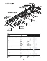
Connect the cables coming from the video sources, the serial
cable coming from the external device and the fibres for
connection to the Display, to the rear panel of the DigiOptical
Image Processor.
To obtain the best performance from the RTX system, connect
the various signal sources using good quality cables designed
for video applications (impedance characteristic 75
Ω
).
Make sure:
•
to arrange the cables so that they are not a hindrance to
people moving around;
•
to carefully insert the cables in the connectors so as not to
damage the feet;
•
not to twist or crush the cables;
•
not to tear the cables when disconnecting them from the
various devices.
Video sources (television receivers, VCRs, DVD players, etc.)
often have several outputs. To obtain the best performance from
your system, carefully choose which output to use. Generally,
the type of signal offering the best image quality is DVI-D, followed
by RGB, Components, S-Video and Composite Video, in that
order.
However, the RTX system is equipped with an excellent Video
Decoder and De-Interlacer and therefore even inferior quality
signals will produce extremely satisfactory results.
Table 2 shows the types of signals usually available for the most
common types of video sources and the connectors to use on
the DigiOptical Image Processor for their respective inputs.
VIDEO
Apply a Composite Video signal (CVBS) to these inputs through
a cable with an RCA-type connector.
The connector on the source is generally yellow and the
respective label often has the word VIDEO.
Although other types of signals are preferable (since they allow
better image quality), it is still the most used type of output and
nearly all television receivers, VCRs, DVD players, video
cameras, etc., are equipped with it.
S-VIDEO
Apply an S-Video signal to these inputs through a cable with a
mini-DIN type connector.
The corresponding output on the source can be identified by
the wording S-VIDEO or Y/C.
Almost as widespread as Composite Video, it is preferable since
it offers a clearer and sharper image.
COMPONENT/RGBS
These inputs appear as three sets of 5 RCA connectors
(5,6,7) and a set of 5 BNC connectors (8).
RGB and Component signals can be applied to each set of
connectors.
RGB signals can have composite synchronism on the green
signal (RGsB), composite synchronism on the HV signal or
separate synchronisms on the H and V signals.
Connect the R, G, B outputs of the source to the respective R,
G, B inputs of the DigiOptical Image Processor (paying attention
not to switch them) and any synchronism signals to the HV or H
and V inputs. Regarding the three sets of RCA connectors, the
colours will help you perform the operation: the R connector is
red, G is green, B is blue, H/HV is white and V is black.
By using a suitable cable for adapting from SCART to RCA (or
BNC) type connectors, an RGB video signal coming from a
source equipped with an SCART plug output can be applied to
this input.
Component signals are connected to inputs Y, Cr and Cb, paying
attention to maintain the correspondence with the outputs on
the source.
Since the latter can be labelled in various ways, refer to Table 1
to establish the correspondences between the various signals.
The connector colours can also be of help, as shown in the table.
for even the most demanding installations.
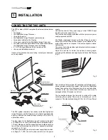
During installation of the optical fibre cable:
•
Take particular care in handling the fibres: only handle the
cable ahead of the unravelling point (Fig. 3). Only pull on the
cable, not on the fibres or connectors.
•
Only remove the protection plug covering the ferrula when
inserting in the connector: if it should come in contact with
other bodies it could be damaged and rendered unusable.
•
Take particular care inserting the fibres in their respective
connectors, which are located on the rear panel of the
DigiOptical Image Processor and the back of the Display (Fig.
5).
•
Make sure that the fibres are not switched: make sure the
numbers shown on the fibres match those on the connectors.
•
Check that the connectors are correctly inserted.
•
Use the special cable clamps located on the rear panel of
the Display to prevent the connectors from being subjected
to pulling or levering.
•
Make sure that the cable is not an obstacle for persons along
its path.
•
Take care not to create knots in the cable and that it does not
form an arc with radius of less than 2 cm (0.8 in) when curved.
•
Keep the cable from being pulled or jerked, as this could pull
out the connectors and damage them.
DigiOptical
Image Processor
Connector
Y (green)
Y
Cr (red)
P
Cb (blue)
R
Y
R-Y
Y
V
P
B
B-Y
U
Video signal
source connector
Table 1
8
7
6
5

