background image


14 


ENGLISH 

10.3


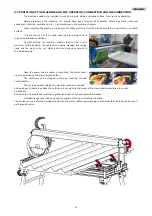
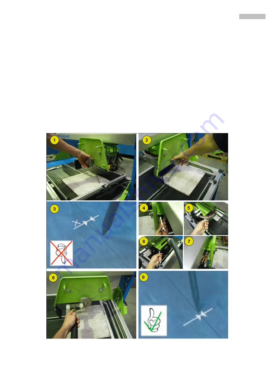
GUIDEWAY ALIGNMENT BLADE 

The cutter VENUS MKNO model are shipped well regulated so that when mounting the blade cut at an angle of either 
90°. If for some unforeseen blow or any other cause to be off, go to the nearest service center for repair 

To perform this operation is necessary to provide a steel rod with 4 or 5mm diameter and 350mm long 

approximately sharpened at one end in the form of pencil-point. Also need a piece of ceramic (tile or sandstone) and 
white chalk. It will proceed as follows: 


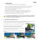
Unplug the machine from electricity and remove the disk safeguard.  


Loosen the blocking controls from both ends and with the square located on the cutting table and facing the 

front side of the disk, you need observe the parallelism of both.  


Place the rod between the flanges for fixing the disk and tighten the axle nut, so that the pointed end of the rod 

friction with the work piece in the area marked with chalk. 


Move the sliding cart so that the rod makes a straight line on the tile. 

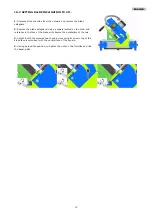
Then turn the shaft so that the rod be on the opposite side move the tray in reverse way to the one perform before 
in order to draw a new line, this must match exactly with the first. If both lines are mismatched, to loosen the 
screws on the blade spindle bearings leaving them with a pinch moderate and adjust the position of this until we 
get the two on the chalk lines are coincident. Once achieved will turn to tighten the screws of the engine 


Replace the blade and the safeguard 


Summary of Contents for VENUS 125 POLYPANEL

Page 1: ...POLYPANEL...

Page 2: ...1 ESPA OL...

Page 3: ...N DISCO DE CORTE 9 9 INSTRUCCIONES DE PUESTA EN MARCHA Y USO 10 9 1 MONTAJE 10 9 2 POSICI N DE MAQUINA Y OPERARIO CONEXI N Y DESCONEXI N 11 10 MANTENIMIENTO 12 10 1 AJUSTE DE LA INCLINACI N DEL DISCO...

Page 4: ...a unidad de corte se realiza manualmente mediante un volante Este modelo de m quina est fabricado con materiales de primera calidad Cualquier otro uso que se le pueda dar a esta m quina se considera i...

Page 5: ...TECCI N AC STICA LEER EL MANUAL DE INSTRUCCIONES ES OBLIGATORIO EL USO DE GUANTES NIVEL DE POTENCIA AC STICA EMITIDO POR LA M QUINA Maquina conectada a 110V Maquina conectada a 230V Maquina conectada...

Page 6: ...quina y cuando haya que desplazarla dentro del lugar de trabajo se consigue hacerlo manualmente con una persona o con carretillas ATENCI N Bloquee la unidad de corte antes de desplazar la m quina par...

Page 7: ...energ a el ctrica de la red ATENCI N Desconectar la m quina de la red antes de proceder a cambiar la posici n de las plaquitas puente en los motores Tambi n deber proceder a cambiar las etiquetas adh...

Page 8: ...to Sea precavido y no permita la presencia en el entorno de la m quina cuando est en funcionamiento Prohibir el acceso y manipulaci n de la m quina a personas que no se hallan familiarizado antes con...

Page 9: ...avance corte 3 Resguardo disco 4 Pisador 5 Disco 6 Bloqueo patas antigiro 7 Motor 8 Manivela regulaci n altura de corte 9 Regla frontal 10 Bancada 11 12 Interruptor 13 Manivela regulaci n ngulo de co...

Page 10: ...TO DE MONTAJE O SUSTITUCI N DE UN DISCO DE CORTE Para montar o sustituir el disco se proceder de la siguiente forma Comprobar que el cable de alimentaci n esta desconectado del tomacorriente de la maq...

Page 11: ...A Y USO 9 1 MONTAJE Al desembalar la maquina usted tendr que montar los siguientes componentes en funci n del modelo que haya adquirido MONTAJE CADENA PORTACABLES Y SOPORTE PORTACABLES MONTAJE INTERRU...

Page 12: ...el operario debe situarse frente a la m quina en esta posici n podr manejar con facilidad la unidad de corte y tendr siempre accesible el interruptor tomacorrientes Una vez conectado el cable de alim...

Page 13: ...e manual Queda prohibido cualquier tipo de modificaci n en alguna de las piezas elementos o caracter sticas de la m quina que el usuario haga de forma independiente El fabricante no ser en ning n caso...

Page 14: ...situada sobre la bancada y haciendo referencia en la cara del disco observaremos el paralelismo de ambos 3 Regular mediante los tornillos de cada extremo aflojando sus tuercas hasta conseguir que la c...

Page 15: ...bancada con la cara esmaltada hacia abajo e impregne de tiza la parte central de la cara vista Coloque la varilla entre las bridas de fijaci n del disco de forma que la punta afilada roce con la pieza...

Page 16: ...Potencia de corte insuficiente Embotamiento de los segmentos o bandas diamantadas del disco Dar varios cortes a un material abrasivo Arenisca Hormig n Piedra esmeril Disco inapropiado Usar el disco ap...

Page 17: ...OR 2 2KW 3KW TENSI N MOTOR 110V 230V 230V 400V REVOLUCIONES MOTOR 2800 R P M DI METRO M XIMO DISCO 350 mm DI METRO ORIFICIO CENTRAL DISCO 25 4 mm LONGITUD DE CORTE 1250 1250 PROFUNDIDAD CORTE CON DISC...

Page 18: ...de ellos deber ponerse en contacto con el departamento de post venta especificar claramente el n mero con el que est se alado as como el modelo numero de fabricaci n y a o de fabricaci n que aparece...

Page 19: ...SQUEMAS EL CTRICOS 2P T Sonda t rmica 2P T Termal probe 2P T Sonde thermique 3P T Sonda t rmica 3P T Termal probe 3P T Sonde thermique 3P T 3P N T Sonda t rmica 3P N T Termal probe 3P N T Sonde thermi...

Page 20: ......

Page 21: ...SOCIEDAD INDUSTRIAL DE MAQUINARIA ANDALUZA S A POL IND JUNCARIL C ALBU OL PARC 250 18220 ALBOLOTE GRANADA Telf 34 958 49 04 10 Fax 34 958 46 66 45 FABRICACI N DE MAQUINARIA PARA LA CONSTRUCCI N ESPA A...

Page 22: ...POLYPANEL...

Page 23: ...1 ENGLISH...

Page 24: ...TING DISK 9 9 MACHINE STARTING UP AND USING INSTRUCTIONS 10 9 1 ASSEMBLY INSTRUCIONS 10 9 2 POSITION OF THE MACHINE AND THE OPERATOR CONNECTION AND DISCONNECTION 11 10 MAINTENANCE 12 10 1 SETTING BLAD...

Page 25: ...masonry building sites to cut sandwich panel The cutting tool is a widia disk powered by an electric motor The progress of the disk is done manually by moving the cutting head in the direction of the...

Page 26: ...READ INSTRUCTIONS MANUAL USE SAFETY GLOVES SOUND POWER LEVEL ISSUED BY THE MACHINE Machine connected to 110V Machine connected to 230V Machine connected to 400V Hot surfaces Entry not allowed to perso...

Page 27: ...ORTE After unpacking the machine it can be move it into the work place either manually by one person or by a forklift WARNING Block cutting head before move the machine to prevent unintentional moveme...

Page 28: ...the network before proceeding to change the position of the bridge plates on the engines You should also proceed to change the stickers indicating the supply voltage so there will always be indicated...

Page 29: ...achine to people who are not familiar with the machine before Work clothes should not include loose clothing that could get caught in moving parts of the machine Before starting the machine read the i...

Page 30: ...ideway 2 Transmision 3 Safeguard blade 4 Clamping pads 5 Blade 6 Leg s lock 7 Engine 8 Cutting height adjustment 9 Front rule 10 Bedplate 11 12 Switch 13 Cutting angle adjustment 14 Fixing knob feet 1...

Page 31: ...hat meet the technical requirements and safety requirements and are offered in a range that covers all the needs and facilitates the correct choice 8 1 MOUNTING REPLACING THE CUTTING DISK The disk can...

Page 32: ...NSTRUCTIONS 9 1 ASSEMBLY INSTRUCIONS After you unpack the machine you will need to assemble the following components depending on the model you purchased TOW CHAIN ASSEMBLY AND BASE TOW CHAIN SWITCH A...

Page 33: ...in from of the machine In this position the operator can easily manage the cutting head and the piece to be cut He she will also have easy access to the electrical plug Once the power supply cable is...

Page 34: ...in this manual It is prohibited to independently make any change in some parts components or characteristics of the machine The manufacturer shall in no case be responsible for the consequences that...

Page 35: ...ard Using a square located on the main and reference in the face of the blade will observe the parallelism of the two 3 Adjust it with the screws at each end by loosening its screws to get the blade f...

Page 36: ...are located on the cutting table and facing the front side of the disk you need observe the parallelism of both Place the rod between the flanges for fixing the disk and tighten the axle nut so that t...

Page 37: ...it Cutting power insufficient Bluntness of the disk segments or diamond bands Effectuate different cuts on an abrasive material Sandstone concrete stone emery Inappropriate disk Use appropriate disk...

Page 38: ...125 125 Motor power 2 2KW 3KW MOTOR TENSION 110V 230V 230V 400V MOTOR RPM 2800 R P M Outer disk diameter 350 mm Inner disk diameter mm 25 4 mm Cutting length 1250mm 1250mm Cutting dept 350 100 mm Net...

Page 39: ...may be download through our website To order any spare part please contact our alter sales service clearly indicating the serial number of the machine model manufacturing number and year of manufactu...

Page 40: ...LECTRICAL SCHEMES 2P T Sonda t rmica 2P T Termal probe 2P T Sonde thermique 3P T Sonda t rmica 3P T Termal probe 3P T Sonde thermique 3P T 3P N T Sonda t rmica 3P N T Termal probe 3P N T Sonde thermiq...

Page 41: ......

Page 42: ...SOCIEDAD INDUSTRIAL DE MAQUINARIA ANDALUZA S A POL IND JUNCARIL C ALBU OL PARC 250 18220 ALBOLOTE GRANADA TEL 34 958 49 04 10 Fax 34 958 46 66 45 MANUFACTURER OF LIGHT MACHINERY FOR CONSTRUCTION SPAIN...

Reviews: