background image

Control Unit 

GFC 16


SIMATEK A/S 

www.simatek.com 
Hotline: +45 4046 7525 
aftersales@simatek.dk 


Doc. No.: 1400003_EN 

Rev.: - 

Date: 04.2017 


Index 


1.


Main features 

3


2.


Tekniske data 

3


3.


Installation guidelines 

4


4.


Preliminary checks 

5


5.


Electrical connections 

5


6.


Settings 

5


7.


Remote 

7


8.


Shut down cleaning 

7


9.


Troubleshooting 

8


10.


Fuse table 

8


11.


Factory settings/Program menu 

9


12.


Legend 

10


13.


General assembly Simatek GFC 16: 2-16 valves 

11


14.


Electric diagram - Simatek GFC 16: 2–10 valves 

12


15.


Electric diagram - Simatek GFC 16: 12–16 valves 

13


16.


Declaration of conformity 

14


NOTE! Figures shown inside square brackets […] refer to positions on page 11. 


CAUTION! 

Before use, read the instructions thoroughly to acquire sufficient knowledge of the product. For your 

convenience, keep this sheet as a quick reference.  

Subject to change without notice. 


Note: The GFC 16 unit is to be installed by trained personnel only! 


Summary of Contents for GFC 16

Page 1: ...Manual Control Unit GFC 16 1400003_EN 04 2017...

Page 2: ...tings Program menu 9 12 Legend 10 13 General assembly Simatek GFC 16 2 16 valves 11 14 Electric diagram Simatek GFC 16 2 10 valves 12 15 Electric diagram Simatek GFC 16 12 16 valves 13 16 Declaration...

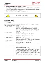
Page 3: ...n terminal blocks with max wire section of 2 5 mm Temperature Storage 20 C 80 C Operating 10 C 50 C with duty cycle 30 Voltage available Input 230 V 10 50 60 Hz Output 115 230 24V AC 24 V DC Input 115...

Page 4: ...A disconnecting switch has to be installed on the power line before the control unit Do not attempt to repair the control unit contact Simatek All wiring has to be carried out by a qualified electric...

Page 5: ...ace the terminals cover and replace the screws 20 6 Settings 6 1 Voltage selection CHECK 1 That Simatek GFC 16 does not have power on off switch 1 on 0 and terminals 4 disconnected 2 That the supply v...

Page 6: ...nected Simatek GFC 16 4 then 4 valves will be recognized Simatek GFC 16 12 then 12 valves will be recognized 2 Press SELECT MENU 9 2 will flash on display 7 Using keys 10 select Pulse time 0 01 9 99 s...

Page 7: ...to start the cleaning cycle again from the position it stopped 8 Shut down cleaning We suggest operating one or more cycles of Shut down cleaning at the end of each working session in order to remove...

Page 8: ...rupted Check coils continuity Display shows the pulsing sequence but valves are not functioning The secondary of the transformer is interrupted Contact Simatek Power circuit is damaged Contact Simatek...

Page 9: ...type However the pause time must correspond to the compressor capacity compressor shall be able to fill the compressed air tank between each pulse 11 3 Shutdown cleaning cycles Bag cleaning will cont...

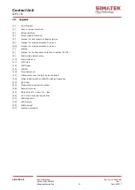
Page 10: ...valves 6A Jumper for voltage selection to valves 7 Display 8 Jumper for the frequency selection to valves AC DC 9 Push button Select menu 10 Push buttons 11 LED Pulse 12 LED Pause 18 LED OK 20 Termina...

Page 11: ...Control Unit GFC 16 SIMATEK A S www simatek com Hotline 45 4046 7525 aftersales simatek dk 11 Doc No 1400003_EN Rev Date 04 2017 13 General assembly Simatek GFC 16 2 16 valves...

Page 12: ...Control Unit GFC 16 SIMATEK A S www simatek com Hotline 45 4046 7525 aftersales simatek dk 12 Doc No 1400003_EN Rev Date 04 2017 14 Electric diagram Simatek GFC 16 2 10 valves...

Page 13: ...Control Unit GFC 16 SIMATEK A S www simatek com Hotline 45 4046 7525 aftersales simatek dk 13 Doc No 1400003_EN Rev Date 04 2017 15 Electric diagram Simatek GFC 16 12 16 valves...

Page 14: ...Control Unit GFC 16 SIMATEK A S www simatek com Hotline 45 4046 7525 aftersales simatek dk 14 Doc No 1400003_EN Rev Date 04 2017 16 Declaration of conformity...

Reviews: