background image


Manual  

Control Unit GFCD 32 

1400001_EN/05.2017 

Summary of Contents for GFCD 32

Page 1: ...Manual Control Unit GFCD 32 1400001_EN 05 2017...

Page 2: ...10 12 P value playback optional 10 13 Troubleshooting 12 14 Fuse table 12 15 Factory settings Program menu 13 16 Legend 14 17 Simatek GFCD 32 4 20 General assembly 15 18 Electric diagram for Simatek G...

Page 3: ...GFCD 32 approx 3 3 kg Connections Push in plugs with max wire section of 2 5 mm Temperature Storage 20 C 80 C Working 10 C 50 C Voltage available Input 230 V 10 50 60 Hz Output 115 230 24V AC 24 V DC...

Page 4: ...according to the cable used A disconnecting switch has to be installed on the power line before the control unit Do not attempt to repair the control unit contact Simatek All wiring has to be carried...

Page 5: ...the voltage frequency as indicated on the coils 5 Connect the valves to the terminal blocks 2 between terminal C and the numbered outputs 6 Earthing 3 of the valves is necessary when output voltage is...

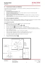
Page 6: ...esponds to the one available from the supply voltage e g both are set to 230 V 4 Should the two voltages be different move the jumpers 5 in order to select the same supply voltage 5 Go to point 7 1B B...

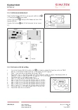
Page 7: ...Cycle 1 99 sec The Shut down cleaning automatically starts when the filter P goes below 0 10 kPa 6 Press SELECT MENU 9 The No 6 will flash on the display 7 Using the keys buttons 10 select the No of C...

Page 8: ...GFCD 32 is in Automatic Mode the LED Manual 30 is off In Automatic Mode the Pause Time depends on the selected Automatic Pause Time 7 3 3 Remote switching It is possible to pass from Automatic Mode t...

Page 9: ...t 0 kPa reconnect 13 the connection pipes between the pressure filtered taps and pressure nipples 13 9 4 LED alarm The LED Alarm 17 switches on if the P inside the filter exceed the P Alarm selected o...

Page 10: ...the assembled board it is possible to broadcast to distance on other unit the P value that is showed on Simatek GFCD 32 display 7 Connect to the terminals 4 20 mA POS and 4 20 mA NEG see page 10 12 1...

Page 11: ...de A0 appears 2 Press until compose on the display the number A879 3 Press Select menu on the display appears the letter C and the number of outlets of the Simatek GFCD 32 Example in case of a Simatek...

Page 12: ...nsformer is disconnected Refer to Simatek Faulty main board Refer to Simatek Power supply to the valves is different from voltages indicated on the coils Move the two jumpers 6 on the position selecti...

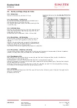
Page 13: ...the whole cleaning sequence See Simatek s filter manual regarding compressed air consumption 15 5 Pause time Shutdown cleaning The pause time during shutdown cleaning may be set as required according...

Page 14: ...tons 11 LED Pulse 12 LED Pause 13 Inlet pressure nozzle 14 Select P Valves button 15 LED LP Low pressure 16 Automatic Manual mode button P Cleaning 17 LED Alarm 18 LED OK 19 Alarm reset button 20 Term...

Page 15: ...Control Unit GFCD 32 SIMATEK A S www simatek com Hotline 45 4046 7525 aftersales simatek dk 15 Doc No 1400001_EN Rev Date 05 2017 17 Simatek GFCD 32 4 20 General assembly...

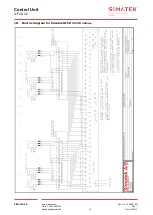
Page 16: ...Control Unit GFCD 32 SIMATEK A S www simatek com Hotline 45 4046 7525 aftersales simatek dk 16 Doc No 1400001_EN Rev Date 05 2017 18 Electric diagram for Simatek GFCD 32 20 valves...

Page 17: ...Control Unit GFCD 32 SIMATEK A S www simatek com Hotline 45 4046 7525 aftersales simatek dk 17 Doc No 1400001_EN Rev Date 05 2017 19 Declaration of Conformity...

Reviews: