background image

Owner’s Manual


 MOON 


i


3.3


Integrated Amplifier


Summary of Contents for MOON i 3.3

Page 1: ...Owner s Manual MOON i 3 3 Integrated Amplifier...

Page 2: ...rticularly at plugs convenience receptacles and the point where they exit from the apparatus 11 Only use attachments and accessories specified by the manufacturer 12 Use only with the cart stand tripo...

Page 3: ...voltage Both the shipping box and rear panel serial number label will indicate the correct voltage Use of any other voltage will likely damage the unit and void the warranty 3 AC extension cords are...

Page 4: ...6 Front Panel Controls 7 Optional Digital Inputs 8 Optional Phono Section 9 Optional Balanced Input 11 Rear Panel Connections 11 SimLink 13 Operating the i 3 3 13 Remote Control Operation 14 Specifica...

Page 5: ...s the pride we have taken in creating this fine audio product We understand the power and emotion of music and build our products with the goal of faithfully capturing these elusive qualities The info...

Page 6: ...e MOON components Four bipolar output devices per channel in the amplification section which offer superb linearity throughout the entire audio frequency spectrum Class A output to 5 watts for greater...

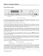
Page 7: ...udspeakers connected to the MOON i 3 3 This feature is very useful when listening to the i 3 3 with headphones When this function is engaged the red LED located to the left of the display window will...

Page 8: ...ts The Digital Input option includes four 4 separate inputs D1 uses an optical Toslink connector D2 and D3 use S PDIF on an female RCA connector and D4 uses a type B USB connector The D1 is intended f...

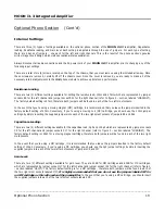
Page 9: ...an optional phono section that may be installed only at an authorized dealer or at the Simaudio factory Circuit Board Layout Figure 3 MOON i3 3 Optional Phono Section Circuit Board Layout ___________...

Page 10: ...of 47k Conversely if you re using a moving coil MC cartridge you should use the 100 jumper settings by simply inserting the supplied jumpers into each of the two right most sockets of jumpers R9 and R...

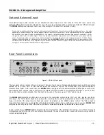
Page 11: ...anel The rear panel will look similar to Figure 4 above There are four 4 pairs of single ended analog inputs on RCA connectors labeled CD A1 A2 and A3 P The left channel inputs are located on top and...

Page 12: ...g posts The right channel speaker output is located above the analog inputs The left channel speaker output is located to the right of the digital inputs Connect your loudspeakers with the cables of y...

Page 13: ...up again Making the AC Connection Connect the supplied AC power cable to the IEC receptacle located on the rear panel of the integrated amplifier s chassis Ensure that the AC wall outlet you use has...

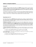
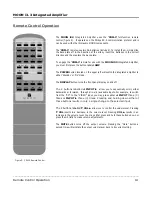
Page 14: ...splay on and off The 2 buttons labelled INPUT allow you to sequentially scroll either backwards or forwards through all six 6 available inputs For example to switch from the CD to the VIDEO input you...

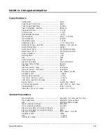
Page 15: ...V s Maximum Current Peak 22 amperes Maximum Current Continuous 12 amperes Frequency Response 2Hz 900kHz 0 3dB Crosstalk 1kHz 88dB Intermodulation Distortion 0 03 THD 20Hz 20kHz 1 watt 0 015 THD 20Hz 2...

Page 16: ...mic Range 116dB Signal to noise ratio 115dB full output Slew Rate 50V s Channel Separation 115dB Low Level Linearity 1 0dB to below 120dBFS Intrinsic Jitter 25 picoseconds RMS Balanced Pin Assignment...

Reviews: