background image


                                                                                                                                                  Smart Machine Smart Decision                        


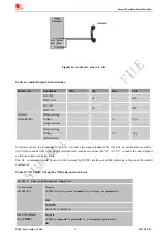
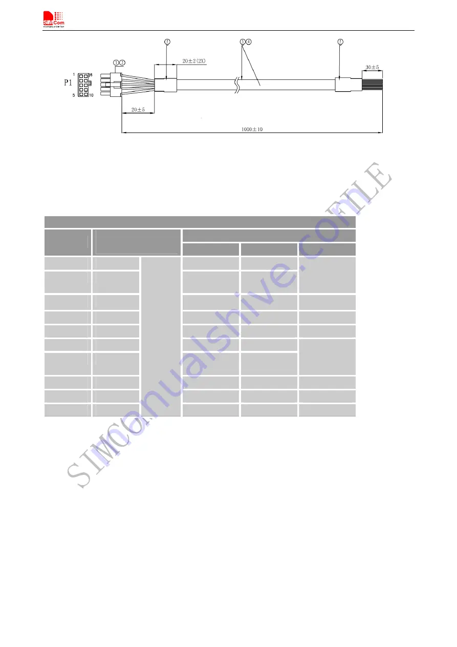
  Figure 13: Dimensions of 10-line cable   


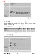
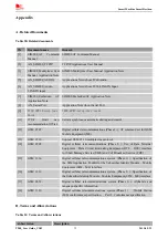
Table 5: signal assignment of 10 pin cable 

Connecting diagram 

Terminal signal 

P1 

Wire color and cutting 

length 

Signal name 

I/O 

Comments 

Green 

 GPIO3 

I/O 

Yellow 

 GPIO1 

I/O 

Configurable 

by AT 

commands  

Black 

GND 


Ground 

Orange 

SPK+ 


Brown 

MIC+  


White 

GPIO4 

I/O 

Gray 

GPIO2 

I/O 

Configurable 

by AT 

commands  

Red 

ADC 


Purple 

SPK-  


10 

Blue 


1007 26# 


MIC-  


6.3.1


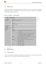
Audio interface 

T900 has one pair of audio input and audio output; it can be connected to a handset directly. 

T900_User Guide_V1.02 

                                                17                       

                                     2013-05-22


Summary of Contents for T900

Page 1: ...T900_User Guide_V1 02 ...

Page 2: ...s possession Furthermore system validation of this product designed by SIMCom within a larger electronic system remains the responsibility of the customer or the customer s system integrator All specifications supplied herein are subject to change Copyright This document contains proprietary technical information which is the property of SIMCom Limited copying of this document and giving it to oth...

Page 3: ... channel 20 6 3 3 GPIO interfaces 21 6 4 Antenna interface 21 6 4 1 Antenna connector 21 6 4 2 Antenna specifications 22 6 4 3 Antenna placement 22 6 5 LED indicator 23 6 6 SIM Card Interface 23 7 Electrical Reliability and Radio Characteristics 25 7 1 Absolute Maximum Ratings 25 7 2 Recommended Operating Conditions 25 7 3 Electro Static Discharge 25 7 4 Operating frequency 26 7 5 Transmitter outp...

Page 4: ...KER VOLUME LEVEL 19 TABLE 9 ADC SPECIFICATION 20 TABLE 10 AT CADC READ ADC 20 TABLE 11 AT SGPIO CONTROL THE GPIO 21 TABLE 12 ANTENNA SPECIFICATIONS 22 TABLE 13 STATUS OF THE NETLIGHT INDICATOR GREEN 23 TABLE 14 AT CSDT SWITCH ON OR OFF DETECTING SIM CARD 23 TABLE 15 ABSOLUTE MAXIMUM RATINGS 25 TABLE 16 RECOMMENDED OPERATING CONDITIONS 25 TABLE 17 THE ESD CHARACTERISTICS TEMPERATURE 25 HUMIDITY 45 ...

Page 5: ...IN ASSIGNMENT RS 232 D SUB 9 POLE FEMALE 15 FIGURE 11 COM PORT PROPERTIES OF THE HYPER TERMINAL 16 FIGURE 12 SIGNAL ASSIGNMENT OF 10PIN I O PORT 16 FIGURE 13 DIMENSIONS OF 10 LINE CABLE 17 FIGURE 14 AUDIO REFERENCE CIRCUIT 18 FIGURE 15 ANTENNA INTERFACE 22 FIGURE 16 INDICATOR LED 23 FIGURE 17 INSTALLATION OF SIM CARD 24 FIGURE 18 MAIN UI 27 FIGURE 19 PARAMETER SETTING 27 FIGURE 20 BROWSE THE SOURC...

Page 6: ...de_V1 02 6 2013 05 22 Version History Date Version Description of change Author 2012 05 3 1 00 Origin Honggang Ma Demin Wu 2012 08 15 1 01 6 3 Correct the PIN assignment Honggang Ma 2013 05 22 1 02 6 3 Correct the signal assignment Honggang Ma ...

Page 7: ...ss 10 class 8 optional and supports the GPRS coding schemes CS 1 CS 2 CS 3 and CS 4 With the help of this document user can understand T900 interface specifications electrical and mechanical quickly Figure 1 T900 overview Note The T900 Terminal is fully complying with RoHS requirements of European standards 2 Key features T900 terminal has the following features 1 Standard AT commands set 2 SIMCom...

Page 8: ...r max 42 8 kbps z Coding scheme CS 1 CS 2 CS 3 and CS 4 z Integrate the TCP IP protocol z Support Packet Broadcast Control Channel PBCCH CSD z Support CSD transmission USSD z Unstructured Supplementary Services Data USSD support SMS z MT MO CB Text and PDU mode z SMS storage SIM card FAX Group 3 Class 1 SIM interface Support SIM card 1 8V 3V External antenna SMA type RF connector Audio features Sp...

Page 9: ...Size 98 60 23mm Weight 125g Firmware upgrade Firmware upgradeable by RS232 interface T900 does work at this temperature but some radio frequency characteristics may deviate from the GSM specification 3 Terminal dimensions T900_User Guide_V1 02 9 2013 05 22 ...

Page 10: ...chanical dimensions of T900 Unit mm 4 Installation The terminal can be fixed by two kickstands Optional that provided by SIMCom the following figure is the illustration Figure 3 Installation of the terminal T900_User Guide_V1 02 10 2013 05 22 ...

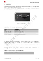
Page 11: ...IN I O port for power supply z The 10 PIN I O port for audio GPIOs and ADC z The standard RS232 interface z LED indicator for power Red and GSM Netlight Green z SIM card holder Figure 4 T900 interface Front view Figure 5 T900 interface Back view Note For the I O interface SIMCom could provide 4 line cable and 10 line cable optional to assist developers it will be introduced at the following chapte...

Page 12: ...art Machine Smart Decision 5 2 T900 Functional Diagram The following figure shows a functional diagram of T900 and typical accessories T900_User Guide_V1 02 12 2013 05 22 Figure 6 T900 functional diagram ...

Page 13: ...al F 10 Line cable Optional G 4 Line power line Optional 6 Application Interface 6 1 Power Supply Customer can use the DC adapter that SIMCom provides as the power source If customer does not use the adapter then DC source should be satisfied with the following requirements z Input voltage range 5 30V z Normal voltage 12V z Current ability 1A T900_User Guide_V1 02 13 2013 05 22 ...

Page 14: ...owing figure shows and table 3 gives a detailed description Table 3 The power line assignment PIN Number Colour Item 1 white NC 2 Red Power 3 Yellow NC 4 Black Ground Figure 8 dimensions of power line Unit mm Figure 9 Power interface When a valid power appears the terminal will power up automatic for the MCU that inside the terminal processed the power up part MCU also acts as a Watch Dog when the...

Page 15: ...1 DCD O Data Carrier Detected 2 RXD O Receive Data 3 TXD I Transmit Data 4 DTR I Data Terminal Ready Attention The ignition of T900 Terminal is activated via a rising edge of high potential 3 15 V 5 GND Ground 6 DSR O Data Set Ready 7 RTS I Request To Send 8 CTS O Clear To Send 9 RING O Ring Indication Note T900 supports autobauding Autobauding allows T900 to automatically detect the baud rate of ...

Page 16: ...nterface T900 provides a 10 PIN I O interface for customer use including Audio GPIOs and 1 ADC channel The following figure gives a brief view of signal assignment Figure 12 signal assignment of 10PIN I O port To make the usage conveniently SIMCom provides a cable for customer it can be inserted to the 10 PIN I O port so customer can develop their application by connecting some devices Figure 13 s...

Page 17: ...e I O Comments 1 Green GPIO3 I O 2 Yellow GPIO1 I O Configurable by AT commands 3 Black GND Ground 4 Orange SPK O 5 Brown MIC I 6 White GPIO4 I O 7 Gray GPIO2 I O Configurable by AT commands 8 Red ADC I 9 Purple SPK O 10 Blue 1007 26 MIC I 6 3 1 Audio interface T900 has one pair of audio input and audio output it can be connected to a handset directly T900_User Guide_V1 02 17 2013 05 22 ...

Page 18: ...arly And if the sound a little lower on the terminal side customer can use the AT CLVL to make the sound higher so that customer can hear clearly The AT commands should be send to the terminal by RS232 interface and the following table shows the detail commands Table 7 AT CMIC Change the Microphone Gain Level AT CMIC Change the Microphone Gain Level Response CMIC list of supported channel s list o...

Page 19: ... 5 dB 8 12 0 dB 9 13 5 dB 10 15 0 dB 11 16 5 dB 12 18 0 dB 13 19 5 dB 14 21 0 dB 15 22 5 dB Example AT CMIC 0 10 This command used to set the terminal MIC gain level to 15db Table 8 AT CLVL Change the Speaker Volume Level AT CLVL Loud Speaker Volume Level Response CLVL list of supported level s OK If error is related to ME functionality CME ERROR err Test Command AT CLVL Parameter See Write Comman...

Page 20: ...details 6 3 2 ADC channel T900 provides an auxiliary ADC which can be used to measure the voltage User can use AT command AT CADC to read the voltage value Table 9 ADC specification Parameter Min Typ Max Unit Voltage range 0 2 8 V ADC Resolution 10 bits Sampling rate 200K Hz Note the maximum voltage that the ADC can gather is 2 8V Table 10 AT CADC Read ADC AT CADC Read ADC Response CADC list of su...

Page 21: ...tion 0 Set the GPIO function including the GPIO output and GPIO as the Keypad 1 Read the GPIO level Please note that only when the gpio is set as input user can use parameter 1 to read the GPIO level otherwise the module will return ERROR GPIO The GPIO you want to be set It has relations with the hardware please refer to the hardware manual function Only when Operation is set to 0 this option take...

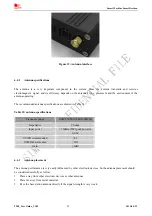
Page 22: ...le 12 Table 12 antenna specifications Frequency range GSM 850 900 1800 1900MHz Impedance 50 ohm Input power 33dBm 2W peak power in GSM VSWR recommended 2 1 VSWR absolute max 10 1 Gain 3dBi 6 4 3 Antenna placement The antenna performance is very easily influenced by other electronic devices So the antenna placement should be considered carefully as follow 1 Place away from other electronic devices ...

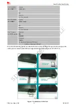
Page 23: ... Off T900 registered to the network 64ms On 300ms Off GPRS communication is established 6 6 SIM Card Interface The SIM interface complies with the GSM Phase 1 specification and the new GSM Phase 2 specification for FAST 64 kbps SIM card Both 1 8V and 3 0V SIM card are supported The SIM interface is powered from an internal regulator inside the terminal T900 supports SIM card hot plug which means t...

Page 24: ...K ERROR Write Command AT CSDT mode Parameter mode 0 Switch off detecting SIM card 1 Switch on detecting SIM card Note when the detecting function is activated the status of sim card will auto report via the serial port The sensing of a hot removal of the SIM is not supported during power saving mode AT CFUN 4 T900_User Guide_V1 02 24 2013 05 22 Figure 17 Installation of SIM Card ...

Page 25: ...ese parameters are for digital interface pins such as GPIO UART and DEBUG 7 2 Recommended Operating Conditions Table 16 Recommended operating conditions Symbol Parameter Min Typ Max Unit VBAT Power supply voltage 5 12 30 V TOPER Operating temperature 40 25 85 TSTG Storage temperature 45 90 7 3 Electro Static Discharge T900 is an ESD sensitive component so more attention should be paid to the proce...

Page 26: ... and receiver sensitivity are shown as bellow Table 19 Transmitter output power and receiver sensitivity Mode Power dBm Sensitivity dBm GSM 850 33 108 E GSM 900 33 108 DCS 1800 30 107 PCS 1900 30 107 8 Software Firmware Upgrade The software can be upgraded via the RS232 interface with the help of tools provided by SIMCom 8 1 Tool introduction The tool name is SIM900 Series download Tools Customer ...

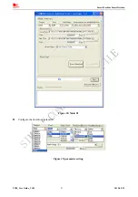
Page 27: ...Smart Machine Smart Decision Figure 18 Main UI z Configure the download parameter Figure 19 parameter setting T900_User Guide_V1 02 27 2013 05 22 ...

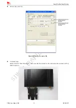
Page 28: ...n z Browse the source file Figure 20 Browse the source file z Terminal setup Before click the Start Download make sure that the terminal is off and connect the terminal to PC by RS232 interface T900_User Guide_V1 02 28 2013 05 22 ...

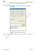
Page 29: ...up z Software download Click the button then the window will change like the following figure shows Figure 22 click download button without power up When the status window shows Power On Reset Target powering up the terminal by connecting the DC source T900_User Guide_V1 02 29 2013 05 22 ...

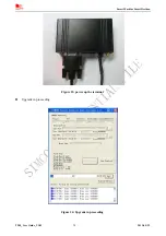
Page 30: ...Smart Machine Smart Decision Figure 23 power up the terminal z Upgrade in proceeding Figure 24 Upgrade in proceeding T900_User Guide_V1 02 30 2013 05 22 ...

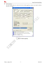
Page 31: ... Smart Decision z Finish upgrading Now the software is the new version click Exit to finish upgrading customer can check the software version by AT GSV Figure 25 Finish upgrading T900_User Guide_V1 02 31 2013 05 22 ...

Page 32: ...elecommunications Phase 2 AT command set for GSM Mobile Equipment ME 13 GSM 07 10 Support GSM 07 10 multiplexing protocol 14 GSM 07 05 Digital cellular telecommunications Phase 2 Use of Data Terminal Equipment Data Circuit terminating Equipment DTE DCE interface for Short Message Service SMS and Cell Broadcast Service CBS 15 GSM 11 14 Digital cellular telecommunications system Phase 2 Specificatio...

Page 33: ...cations HR Half Rate IMEI International Mobile Equipment Identity Li ion Lithium Ion MO Mobile Originated MS Mobile Station GSM engine also referred to as TE MT Mobile Terminated NC NO Connect NA Not Access PAP Password Authentication Protocol PBCCH Packet Broadcast Control Channel PCB Printed Circuit Board PCL Power Control Level PCS Personal Communication System also referred to as GSM 1900 PDU ...

Page 34: ...where blasting operations are in progress Operation of any electrical equipment in potentially explosive atmospheres can constitute a safety hazard Your cellular terminal or mobile receives and transmits radio frequency energy while switched on RF interference can occur if it is used close to TV sets radios computers or other electric equipment Road safety comes first Do not use a hand held cellul...

Page 35: ..._User Guide_V1 02 35 2013 05 22 Contact us Shanghai SIMCom Wireless Solutions Ltd Add SIM Technology Building No 633 Jinzhong Road Changning District Shanghai P R China 200335 Tel 86 21 3235 3300 Fax 86 21 3235 3301 URL www sim com wm ...

Reviews: