background image

20123476 (1) - 07/2016

Istruzioni per installazione, uso e manutenzione
Installation, use and maintenance instructions

Bruciatori di gasolio
Light oil burners

Funzionamento monostadio
One stage operation

CODICE - CODE

MODELLO - MODEL

20121960

RDB2.2R BG2 BLU 25

20121961

RDB2.2R BG3 BLU 35

I

GB

Summary of Contents for 20121960

Page 1: ...zione uso e manutenzione Installation use and maintenance instructions Bruciatori di gasolio Light oil burners Funzionamento monostadio One stage operation CODICE CODE MODELLO MODEL 20121960 RDB2 2R B...

Page 2: ...Istruzioni originali Translation of the original instructions...

Page 3: ...Sistema monotubo 13 5 8 1 Innesco pompa 13 6 Messa in funzione taratura e funzionamento del bruciatore 14 6 1 Note sulla sicurezza per la prima messa in funzione 14 6 2 Regolazione della combustione 1...

Page 4: ...7 1 Generale 22 7 7 2 Diagramma a blocchi per ingresso nel menu 22 7 7 3 Test di spegnimento 23 7 7 4 Post ventilazione 23 7 7 5 Funzionamento intermittente 23 7 7 6 Visualizzazione dell ultimo blocc...

Page 5: ...seguenti Norme Tecniche EN 267 EN 12100 e secondo quanto disposto dalle Direttive Europee MD 2006 42 CE Direttiva Macchine LVD 2014 35 UE Direttiva Bassa Tensione EMC 2014 30 UE Compatibilit Elettroma...

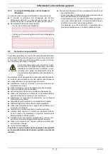
Page 6: ...tamente eseguite possono causare danni alla macchina e o alla persona PERICOLO PERICOLO COMPONENTI IN TENSIONE Questo simbolo contraddistingue operazioni che se non correttamente eseguite comportano s...

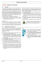
Page 7: ...cose qualora i danni stessi si ano riconducibili ad una o pi delle seguenti cause installazione messa in funzione uso e manutenzione del bruciatore non corretti utilizzo improprio erroneo ed irragion...

Page 8: ...lusivamente le parti previste dal costrut tore 3 2 Addestramento del personale L utente la persona o l ente o la societ che ha acquistato la macchina e che intende usarla per gli usi concepiti allo sc...

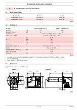
Page 9: ...ce RDB2 2R BG2 BLU 25 1 230V 50Hz 20121960 RDB2 2R BG3 BLU 35 1 230V 50Hz 20121961 Modello RDB2 2R BG2 BLU 25 RDB2 2R BG3 BLU 35 Portata 1 Potenza termica 1 kg h kW 2 1 25 2 95 35 Combustibile Gasolio...

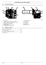
Page 10: ...hermo isolante 5 Vite di regolazione serranda aria 6 Presa d aria CF 7 Vite regolazione pressione pompa 8 Attacco manometro 9 Sensore UV 10 Tubo fiamma 11 Condensatore 12 Motore 13 Riscaldatore PTC 4...

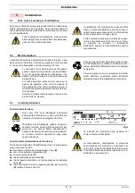
Page 11: ...ttuare ancora pi frequentemente pulizia e manutenzione ATTENZIONE Le operazioni di movimentazione del bruciatore possono essere molto pericolose se non effettua te con la massima attenzione allontanar...

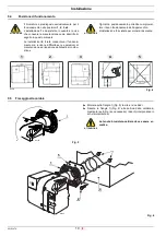
Page 12: ...3 e 4 L installazione 1 da preferire in quanto l unica che consente la manutenzione come descritto di seguito in questo manuale Le installazioni 2 3 e 4 consentono il funziona mento ma rendono diffic...

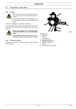
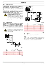
Page 13: ...torno 3 Vite di by pass 4 Attacco manometro 5 Regolatore di pressione 6 Attacco vacuometro 7 Valvola 8 Presa di pressione ausiliaria ATTENZIONE Accertarsi prima di mettere in funzione il brucia tore c...

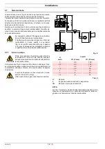
Page 14: ...o L lunghezza massima del tubo di aspirazione I D diametro interno dei tubi dell olio NOTA La Tab C mostra le lunghezze approssimative massime per la tubazione di alimentazione a seconda del dislivell...

Page 15: ...vello L lunghezza massima del tubo di aspirazione I D diametro interno dei tubi dell olio NOTA Le Tab D e Tab E mostrano le lunghezze approssimative mas sime per la tubazione di alimentazione a second...

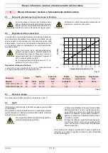
Page 16: ...a in funzione del bruciatore deve essere effettuata da personale abilitato secondo quanto riportato nel presente manuale ed in con formit alle norme e disposizioni di legge vigenti ATTENZIONE Verifica...

Page 17: ...a dell ugello pressione o depressione in camera di combustione eccesso d aria necessario Tutte queste condizioni possono richiedere una diversa regola zione della serranda 6 6 Posizionamento degli ele...

Page 18: ...to del brucia tore almeno 1 volta ogni 24 ore Fare riferimento agli schemi elettrici La sicurezza elettrica dell apparecchio raggiunta soltanto quando lo stesso correttamente collegato ad un effi cace...

Page 19: ...da a quella indicata sulla targhetta di identificazione e in questo manuale La sezione dei conduttori deve essere di min 1 mm2 Salvo diverse indicazioni di norme e leggi locali ATTENZIONE Provare il b...

Page 20: ...tilazione t4i Tempo totale di accensione t4l Tempo di reazione per l attuazione del blocco di sicurezza a causa della mancanza di fiamma t5i Tempo di post accensione ts Tempo di sicurezza tpp Tempo di...

Page 21: ...in caso di assenza di fiamma durante il funzionamento al termine dell ultimo tentativo conseguente alla mancanza di fiamma l apparecchiatura di controllo va in blocco 3 ripetizioni tpp Tempo di post v...

Page 22: ...iva e pu essere eseguita al massimo 2 volte Se al 24 secondo sparisce la fiamma parassita o la luce estranea parte il tempo di pre ventilazione e se si ripresenta la fiamma parassita o la luce estrane...

Page 23: ...14 Controllo del circuito elettronico di comando della valvola dell olio L apparecchiatura di controllo rileva la presenza di un guasto in terno al circuito elettronico di comando della valvola dell...

Page 24: ...SPEGNIMENTO VENTILAZIONE 20 SEC ULTIMO BLOCCO MEMORIZZATO 25 SEC 4 VERDE 10 SEC DOPO IL RILASCIO S9510 5 SEC 10 SEC STATO BRUCIATORE TIPO DI FUNZIONE NUMERO USCITA LAMPEGGI Fig 18 TEMPO DI RILASCIO PU...

Page 25: ...i calore si blocca durante il lampeggio del led si verifica l uscita dal men ma il valore di regolazione rimane memorizzato 7 7 5 Funzionamento intermittente Sequenza per l abilitazione la disabilitaz...

Page 26: ...n viene rilevata fiamma dopo il tempo di sicurezza Dopo 5 secondi dall attivazione della valvola dell olio ROSSO Sempre ON rilevatore di fiamma guasto o sporco valvola olio guasta o sporca guasto al t...

Page 27: ...riodicamente le condizioni dei tubi flessibili Da sostituire almeno ogni 2 anni Controllare che il loro stato sia buono Cisterna In presenza di acqua o contaminazione nella cisterna neces sario rimuov...

Page 28: ...tutte le spi ne e le prese La presa di corto circuito non colle gata 0 5 sec ON 2 5 sec OFF Controllare il corretto inserimento Il bruciatore va in blocco prima o durante la pre ventilazione o post ve...

Page 29: ...pe system 12 5 7 1 Priming pump 12 5 8 One pipe system 13 5 8 1 Priming pump 13 6 Start up calibration and operation of the burner 14 6 1 Notes on safety for the first start up 14 6 2 Combustion adjus...

Page 30: ...7 7 1 General notes 22 7 7 2 Block diagram for entering the menu 22 7 7 3 Shut down test 23 7 7 4 Post purging 23 7 7 5 Intermittent operation 23 7 7 6 Displaying the last lockout that occurred 23 7 8...

Page 31: ...th the following Technical Standards EN 267 EN 12100 and according to the European Directives MD 2006 42 EC Machine Directive LVD 2014 35 UE Low Voltage Directive EMC 2014 30 UE Electromagnetic Compat...

Page 32: ...ed out correctly may cause damage to the ma chine and or injury to people DANGER DANGER LIVE COMPONENTS This symbol indicates operations which if not car ried out correctly lead to electric shocks wit...

Page 33: ...ent of damage to things or injury to people if such damage injury was due to any of the following causes incorrect installation start up use and maintenance of the burner improper incorrect or unreaso...

Page 34: ...Only those parts envisaged by the manufacturer can be replaced 3 2 Personnel training The user is the person body or company that has acquired the machine and intends to use it for the specific purpo...

Page 35: ...ion Voltage Code RDB2 2R BG2 BLU 25 1 230V 50Hz 20121960 RDB2 2R BG3 BLU 35 1 230V 50Hz 20121961 Model RDB2 2R BG2 BLU 25 RDB2 2R BG3 BLU 35 Delivery 1 Thermal output 1 kg h kW 2 1 25 2 95 35 Fuel Lig...

Page 36: ...sulating gasket 5 Air damper adjustment screw 6 Air intake CF 7 Pump pressure adjustment screw 8 Manometer connection 9 UV sensor 10 Flame tube 11 Capacitor 12 Motor 13 PTC Heater 4 5 Burner equipment...

Page 37: ...aning and maintenance are carried out more frequently WARNING The handling operations for the burner can be highly dangerous if not carried out with the great est attention keep any unauthorised peopl...

Page 38: ...nd 4 Installation 1 is preferable as it is the only one that allows the maintenance operations as described in this manual The installations 2 3 and 4 permit operation but make maintenance and inspect...

Page 39: ...14 Key Fig 7 1 Gas oil suction line 2 Return line 3 By pass screws 4 Manometer connection 5 Pressure adjuster 6 Vacuometer connection 7 Valve 8 Auxiliary pressure test points WARNING Before starting t...

Page 40: ...H difference of level L max length of the suction line I D internal diameter of the oil pipes NOTE The Tab C shows the maximum approximate lengths for the sup ply line depending on the difference in...

Page 41: ...f level L max length of the suction line I D internal diameter of the oil pipes NOTE The Tab D and Tab E show the maximum approximate lengths for the supply line depending on the difference in level l...

Page 42: ...p of the burner must be carried out by qualified personnel as indicated in this manual and in compliance with the standards and regula tions of the laws in force WARNING Check the correct working of t...

Page 43: ...ns actual nozzle output positive or negative pressure in the combustion chamber the need of excess air etc All these conditions may require a different air damper setting 6 6 Positioning the electrode...

Page 44: ...you must apply a time switch to L N in series to stop the burner at least once every 24 hours Refer to the wiring diagrams The electrical safety of the device is obtained only when it is correctly con...

Page 45: ...label and in this manual The section of the conductors must be at least 1 mm2 Unless requested otherwise by local standards and legislation WARNING Test the burner by checking the shut down of the bu...

Page 46: ...Total ignition time t4l Reaction time to achieve safety lockout due to flame fail ure t5i Post ignition time ts Safety time tpp Post purging time Only 3 consecutive ignition attempts are permitted F...

Page 47: ...failure during operation the final action at the last attempt following flame failure is a lockout 3 re cycles tpp Post purge time additional purge time at the end of a heat request Can be interrupte...

Page 48: ...at the 24th second the parasite flame or the extraneous light disappears the pre purging time starts and if the parasite flame or the extraneous light reappear the pre purging time is re set and the c...

Page 49: ...lectronic circuit controlling the oil valve The control box detects the presence of a fault inside the elec tronic circuit controlling the oil valve the fault is indicated by the blinking LED see para...

Page 50: ...green Quitting the menu Shut down test 5s t 10s 2 blinks RED none none Automatic at the end of the blink Post purging 10s t 15s 1 blink GREEN 1 10 sec 2 20 sec 3 30 sec 4 60 sec default 5 120 sec 6 0...

Page 51: ...ing the led blinking occur exit menu but the setting value is stored 7 7 5 Intermittent operation Sequence for enable disable Programming allowed in OPERATING mode and in STAND BY Press button for 20...

Page 52: ...is not connected The flame is not detected after the safety time After 5 seconds from oil valve starts RED Steady ON flame detector defective or dirty oil valve defective or dirty faulty ignition tran...

Page 53: ...ly the flexible pipes conditions They have to be replaced at least every 2 years Check to make sure that the hoses are still in good condi tion Fuel tank If water or contamination is present within th...

Page 54: ...ted OFF Check and connect all the plugs and sockets prop erly The short circuit socket is not con nected 0 5 sec ON 2 5 sec OFF Check the proper position The burner goes into lockout mode before or du...

Page 55: ......

Page 56: ...riserva di modifiche Subject to modifications Fonderie Sime S p A via Garbo 27 37045 Legnago Vr Italy Tel 39 0442 631111 Export Division fax number 39 0442 631293 Sime Service fax number 39 0442 6312...

Reviews: